
Online Access
€99.99One-time · 12 months of access
Just €5.88 a module · no auto-renewal
- Read all notes in your browser
- Interactive formulas & diagrams
- Always up-to-date content
- Access from any device
- Requires free account
Sign in to your PART66Online account
One click — no password needed
Don't have an account? Register here
Module 18 — Electric Power Plant
Module 18 was added to Part-66 by Regulation (EU) 2025/111, applicable from 13 February 2026, for subcategory B1.E: aeroplanes with an electric power plant and a maximum take-off mass below 5,700 kg. Every topic in it is set at knowledge level 3. The module examination is 76 multiple-choice questions in 95 minutes, with no essay, and 7 of those questions come from this chapter (AMC1 to Appendix II). This chapter lays the foundations for the rest of the module: what the electric power plant is, how power, torque, speed and efficiency are tied together, the electromagnetism that makes a machine turn, and why heat is the primary constraint on the specific power an electric engine can reach. Where a basic idea is already taught in another module, a short recap is given here with a link to the full treatment.
A propeller does not care what turns it. In a piston aeroplane the shaft is driven by fuel burning in cylinders; in an aeroplane with an electric power plant it is driven by an electric motor fed from a store of electrical energy, usually a battery. Almost everything in this module follows from that substitution. The energy comes from the battery as electric current instead of from burning fuel, it is turned into shaft power by magnetic forces instead of gas pressure, and the heat that every conversion produces has to be carried away by a cooling system, with no hot exhaust stream to take a share of it. This section sets out what Part-66 counts as the electric power plant, how energy travels from the battery to the propeller, how the power-speed behaviour of an electric engine differs from that of a piston engine, and which hazards are new.
EASA's guidance material to Part-66 (GM1 66.A.20(a)) defines the term for the purpose of licence privileges, and it draws the boundary far wider than the motor. The electric power plant is every element of the power plant system that is used to store, transform or convert, control and transmit electrical energy to the parts of the aircraft that provide thrust or lift. The guidance names electrical batteries; fuel cell elements, including the tanks, lines and other circuit elements for their consumables; solar panels; electric engines; cables and connectors; mechanical attachments to the aircraft structure; related instrumentation; and the power output control system.
The useful test is a question of function, not of hardware type: does the item store, convert, control or carry energy on its way to whatever makes thrust or lift? The cables between a propulsion battery and the engine pass that test, so on this aircraft they are power plant, not airframe wiring. The same guidance defines the electrical system of an aircraft with an electric power plant as the electrical power supply source other than the main power plant, plus the distribution system to the aircraft's components and the relevant connectors. A circuit supplying cabin lighting distributes power to an aircraft component, not to a thrust-producing element, so it belongs to the electrical system.
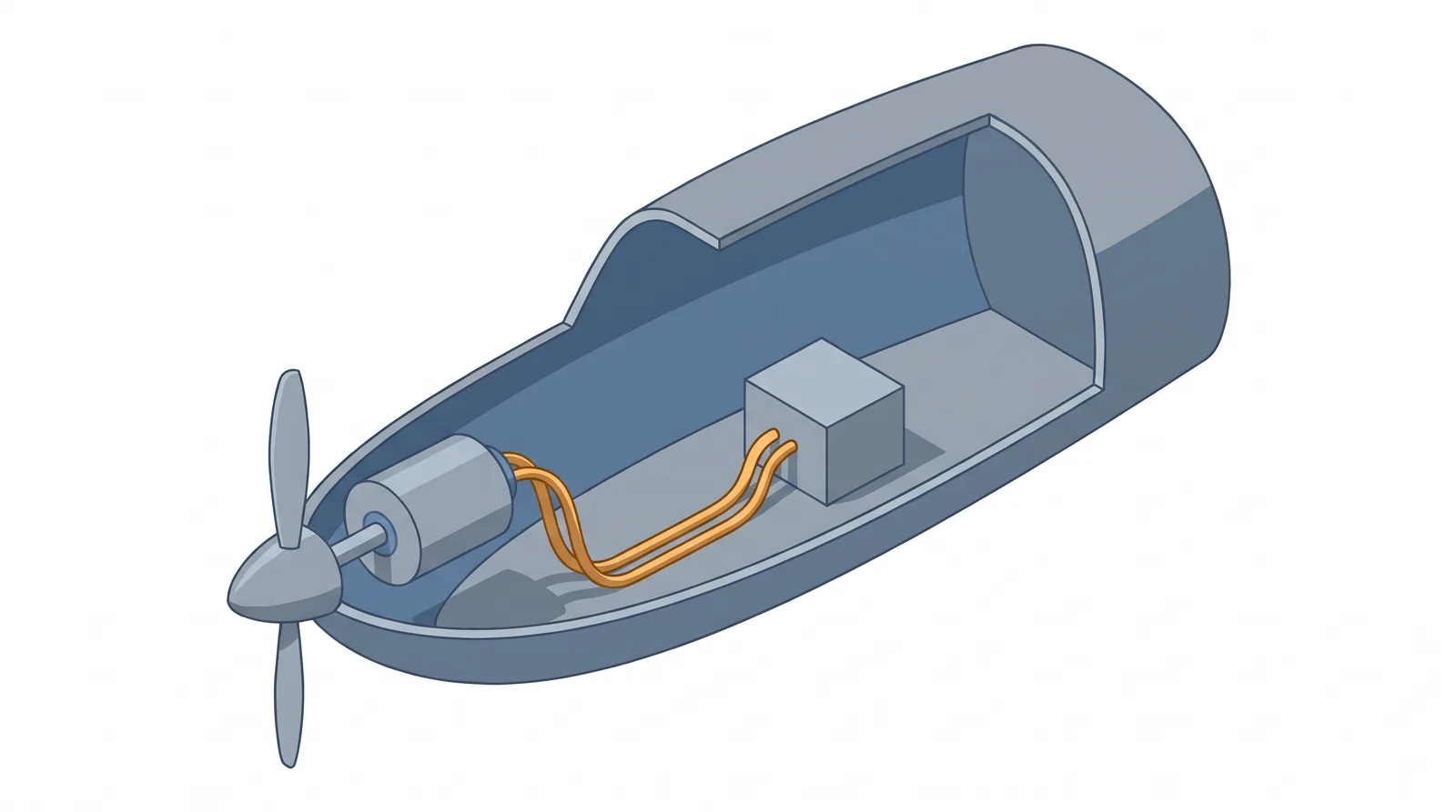
Two exclusions complete the picture. First, hybrid power plant systems that transform fossil-fuel energy into electrical energy for thrust or lift are not covered by "electric power plant". The presence of electric motors does not decide it; the origin of the energy does. Solar panels and fuel cell elements are named inside the definition, so a system converting energy from either source stays inside it. Second, a motor that drives a wheel for taxiing makes neither thrust nor lift. EASA's special condition for electric and hybrid propulsion, SC E-19, states that electric motors driving wheels for taxiing are outside its scope and should be considered part of the landing gear system.
| Item | Where it belongs | Reason |
|---|---|---|
| Propulsion battery, its cables and connectors | Electric power plant | Stores and transmits the energy that becomes thrust |
| Fuel cell elements, with their tanks and lines for consumables | Electric power plant | Named in GM1 66.A.20(a) |
| Solar panels | Electric power plant | Named in GM1 66.A.20(a) |
| Electric engine, its attachments to the structure, related instrumentation, power output control system | Electric power plant | Named in GM1 66.A.20(a) |
| Supply and distribution to cabin lighting and other aircraft components | Electrical system | The supply other than the main power plant |
| Electric motor driving a wheel for taxiing | Landing gear (SC E-19) | Provides neither thrust nor lift |
| Hybrid system turning fossil-fuel energy into electrical energy for thrust | Not an "electric power plant" | Excluded by GM1 66.A.20(a) |
Part-66 decides what a licence holder may certify; certification specifications and special conditions decide what a design must meet, and they use their own vocabulary. EASA Special Condition SC E-19, Issue 1 (April 2021), defines an Electric/Hybrid Propulsion System (EHPS), which may include, among other things, electric engines, turbine engines, piston engines, generators, electrical power generation and distribution, wiring, propulsion batteries, integrated fans, cooling systems, controllers and a power management system. It adds two clarifications: a propulsion battery on its own, with no electric engine, is not an EHPS, but a propulsion battery associated with an electric engine that powers a propeller is. Because an EHPS can include turbine and piston engines, its boundary is not the Part-66 one, which leaves fossil-fuel hybrids out. Each definition does its own job; keep them apart.
SC E-19 applies to systems producing lift, thrust or power for flight, except for CS-22, CS-LSA, CS-23 Level 1 Day VFR and light UAS, and Issue 1 treats any design using hydrogen, whether to feed fuel cells or combustion engines, as outside its scope for now. A special condition binds only a product whose certification basis contains it, so the two EASA-certified electric engines used as examples in this note sit under different rules:
The United States reached the same point by another route. When the FAA issued special conditions for the magniX magni350 and magni650 engines in 2021, it noted that it had never before type certificated an engine that primarily uses electrical technology for propulsion, and that its engine airworthiness standards, 14 CFR part 33, date back to 1964 and do not on their own contain adequate safety standards for such a design. Later sections quote these FAA documents and the NASA X-57 design papers often, and each of them applies only to the product it names.
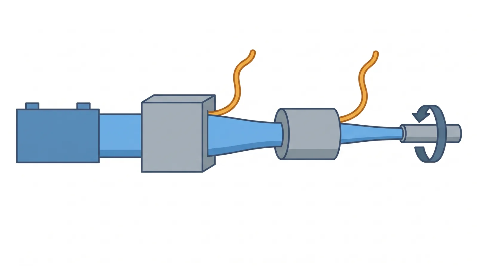
The FAA's description of the magniX engines covers the middle two links. The motor converts electrical energy into mechanical energy by electric current flowing through wire coils, producing a magnetic field that interacts with magnets on the rotating shaft. The controller has two main functional elements: the motor controller and an electric power inverter that drives the motor; the whole unit is sometimes called the inverter. The high-voltage system is the combination of wires and connectors that couples motor and controller. The packaging varies between products: the E-811 is an electric motor associated with its controller, a separate power electronics unit, and the two can be installed independently, while the ENGINeUS integrates the motor and its power electronics in one product. The figure below shows the four links of the chain.
Why an inverter at all? The battery delivers a direct voltage, one that does not alternate, but NASA's work on electric aircraft motors states the requirement plainly: for an electric motor to produce a given torque at a certain speed, electric power must be supplied to it with an appropriate magnitude, waveform and frequency. Frequency matters because the speed of an AC machine is set by the frequency of its supply: a synchronous motor turns exactly at the speed of the rotating field, and an induction motor slightly below it (synchronous speed and slip, in the electromagnetic section below), so a fixed frequency would hold the machine near one speed. The inverter therefore takes in DC and delivers AC whose frequency is adjusted to the speed wanted and whose current is set to give the torque wanted. It does this by switching the DC on and off very rapidly in a controlled pattern, called pulse width modulation (PWM), and NASA expects PWM voltage source inverters to be the dominant form of motor drive in electric aircraft. The transistors that do the switching are covered in Module 4.1.2.
What the controller does with the pilot's lever depends on the design. According to the Velis Electro's Pilot's Operating Handbook, a single power control lever with a magnetic position sensor controls the motor power, and in normal operation the power delivered by the motor is proportional to the lever position. NASA's X-57 cruise motors were commanded in torque instead: each wingtip cruise motor is powered by two independent motor torque controllers that convert the DC power from the batteries into switched AC power based on the torque the pilot commands, and encoders digitise the throttle lever positions, which the controllers use as a torque target. Where SC E-19 applies, its control-system requirements include enabling immediate modulation of EHPS power following a pilot command, with adequate sensitivity, throughout the certified operating envelope. In its special conditions for the BETA H500A engines, the FAA contrasts electric and turbine engines. A turbine's rotor speed is driven by expanding gas and aerodynamic loads on the blades, whereas the speed of an electric engine is directly controlled by electric current and by the electromagnetic field the controller creates. Consequently its rotor responds to a power demand, and to an overspeed-protection system, more quickly and more precisely.
In a piston engine, power and speed are tied together. A NASA study of a low-noise operating mode for propeller-driven electric aeroplanes puts it this way: the mechanical shaft power and shaft speed of reciprocating internal combustion engines are closely coupled, and maximum rated shaft power is typically produced at or near peak shaft speed. Certain electric motors, however, are able to deliver maximum shaft power over a wide range of shaft speed. Induction and synchronous motors, furnished with appropriate power management equipment and speed controllers, vary shaft speed by adjusting the frequency of the power supplied to them. NASA loosely describes the result as an "electronic gearbox" that allows peak rated shaft power to occur at a selectable range of shaft speeds; a piston engine would need a mechanical gearbox with a variable gear ratio to deliver peak shaft power at an arbitrary shaft speed.
Certified data show the idea in practice. The ENGINeUS100B1 data sheet guarantees its minimum maximum-continuous power of 114 kW anywhere in the speed range 1,907 to 2,300 rpm, a band rather than a single point. How torque, voltage and temperature shape that band is the subject of engine performance (18.2).
The same NASA study adds that, unlike air-breathing reciprocating engines, electric motors are insensitive to changes in altitude and, provided they are effectively cooled, insensitive to changes in ambient temperature. That compares shaft-power capability with an engine that breathes air, and it carries a condition; it does not say an electric engine has no environmental limits. Certified engines have them: the E-811 is limited to outside air temperatures from -20 °C to +40 °C, and the ENGINeUS100B1 from -40 °C to ISA+23 °C limited to +38 °C, with a maximum altitude of 15,000 ft. An air-cooled engine also depends on the airflow it receives, and NASA's high-voltage design handbook (written for spacecraft) notes that partial discharge in insulation begins at lower voltages as ambient pressure decreases.
The FAA's reasoning for the magniX engines is a good frame. Electric engines share their basic configuration and function with combustion engines, so they need similar provisions against the common hazards: fire, uncontained high-energy debris and loss of thrust control. But the primary failure concerns, and the probability of exposure to those common hazards, are different. The electric engine uses an electrical energy source instead of aviation fuel and is exposed to chemical, thermal and mechanical operating conditions unlike those in internal combustion systems. High-voltage transmission lines, electromagnetic fields, magnetic materials and high-speed electrical switches form part of its physical make-up.
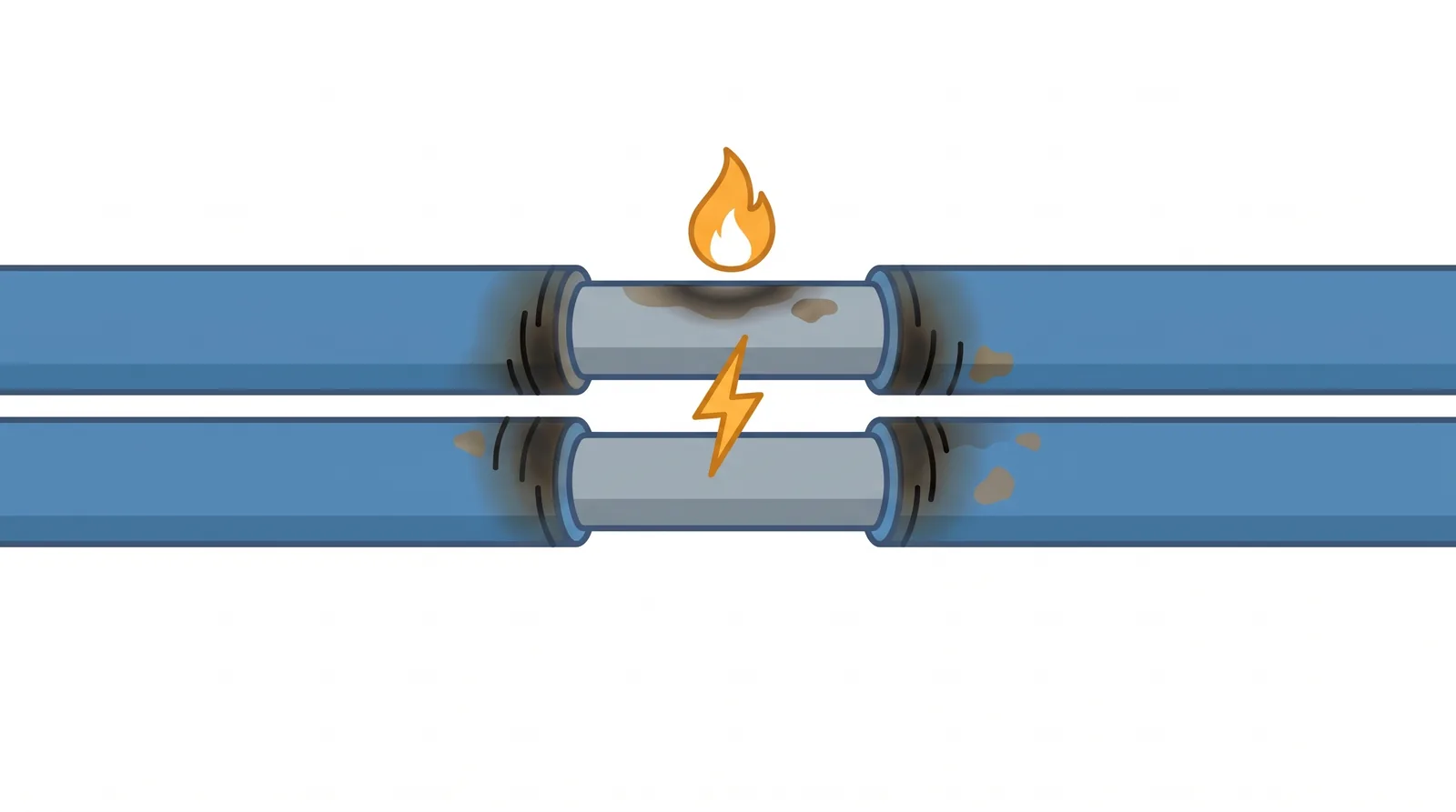
Fire is the clearest example. EASA, explaining how it certified the ENGINeUS, drew the contrast directly: in a combustion engine the risk of fire arises from the ignition of flammable fluids, while in an electric engine it comes from the use of high voltage and from electrical arcing. The FAA describes an arc fault as a high-power discharge of electricity between two or more conductors; the heat it generates can break down the wire's insulation and start an electrical fire.
The special conditions also extend the list of outcomes treated as hazardous. The FAA's magniX conditions add two to the usual hazardous engine effects: electrocution of the crew, passengers, operators, maintainers or others, and blockage of cooling systems that the engine needs to operate within its temperature limits. SC E-19 sets the following as Hazardous EHPS Effects, as a minimum, unless shown not to apply to the intended aircraft application:
Reliability is the last difference. A NASA hazard analysis of urban air mobility concept vehicles found the reliability of electric motors and generators to be a major contributor to lower-than-desired reliability of the electromechanical drivetrain, and past surveys of motor failure modes identify winding insulation and bearings as the dominant causes of motor failure. Both are sensitive to temperature, which is one reason thermal management has its own section at the end of this chapter.
Isolating the battery does not by itself make an electric power plant dead. The power electronics contain capacitors, and EASA's list of practical tasks for electric power plants includes a DC-link capacitor check within the verification of grounding and bonding; a disconnected capacitor can retain its charge. A permanent-magnet engine also generates a voltage whenever its shaft turns, powered or not, as the electromagnetic section below explains. Treat the high-voltage system as live until it has been proved dead at the point of work, following the manufacturer's procedure. The general rules are in Module 7.4.
Four quantities describe what an electric engine delivers: the torque on its shaft, the speed of the shaft, the power that results, and the fraction of the electrical input that arrives as that power. They are not independent. Torque and speed together fix the power; the power and the efficiency together fix how much heat the machine must reject. Work, energy and power in general are covered in Module 3.8; this section applies them to a rotating shaft.
Torque is turning effort, measured in newton-metres. Work done by a torque is torque multiplied by the angle turned through, in radians, so one revolution (\( 2\pi \) radians) at a torque \( T \) does \( 2\pi T \) joules of work. A shaft turning at \( N \) revolutions per minute makes \( N/60 \) revolutions every second, so the work done per second, the power, is \( 2\pi N T / 60 \). The same result is usually written with the angular velocity \( \omega \) in radians per second:
\( P \) in watts, \( T \) in newton-metres, \( \omega \) in radians per second, \( N \) in revolutions per minute. Because \( 60\,000/2\pi \approx 9549 \), power in kilowatts is \( P = T N / 9549 \).
The EASA data sheet for the Pipistrel E-811 gives its maximum continuous power (MCP) as 49.2 kW at 2,350 rpm, with a maximum torque at MCP of 200 N m. Check that the figures agree:
\( \omega = 2350 \times 2\pi / 60 = 246.1 \) rad/s
\( P = 200 \times 246.1 = 49\,220 \) W, about 49.2 kW
The maximum take-off power is 57.6 kW at 2,500 rpm with 220 N m: \( 220 \times 2500 \times 2\pi/60 = 57\,596 \) W, about 57.6 kW. Both ratings obey \( P = T\omega \). Two slips are worth guarding against. Multiplying the torque by the speed in rpm without the \( 2\pi/60 \) conversion gives \( 200 \times 2350 = 470\,000 \), which would read as 470 kW, about 9.5 times too large; a misplaced decimal point gives 4.9 kW. A sanity check catches both: an engine of this size makes tens of kilowatts, not hundreds and not single figures.
The relationship reads both ways. At constant torque, power rises in proportion to speed. At constant power, torque falls as speed rises: 50 kW at 2,000 rpm needs \( 50\,000 / 209.44 = 238.7 \) N m, but at 4,000 rpm only 119.4 N m. Power and torque are therefore not interchangeable, and a high-power motor is not necessarily a high-torque one. NASA's X-57 cruise motor shows the same arithmetic in a rating: 255 N m up to 2,700 rpm, which is \( 255 \times 2700 \times 2\pi/60 \approx 72 \) kW.
NASA's design methods for aircraft permanent magnet synchronous machines start from a common sizing equation that separates the speed from the things that make torque:
\( \tau \) is torque, \( B \) the average magnitude of the radial flux density produced by the rotor, \( A \) the stator electrical loading, \( D \) the stator inner diameter and \( L \) the motor stack length. The speed term \( \omega \) determines the power produced by a given torque; the remaining terms define the torque.
Read as a design statement, the equation says that torque grows with the size of the rotor (\( D^2 L \) is proportional to its volume) and with how hard the magnetic circuit (\( B \)) and the electric circuit (\( A \)) are worked. Neither can be raised without limit: \( B \) is capped by saturation of the iron, covered in the next section, and \( A \) by the heat that current makes in the copper, covered in the last. Speed is the other route to more power. For the same power, a faster motor needs less torque, so it can be smaller, and NASA notes that mechanical gears are often used to reduce the required motor torque and the overall drivetrain weight. The price is the gearbox itself: an ORNL assessment of automotive traction motors points out, for induction motors, that raising the speed always gives a smaller, lighter motor but requires a high-ratio gearbox that has its own mass and losses. Several electric aero engines avoid the gearbox: the ENGINeUS100B1 shaft interfaces directly with the propeller, the FAA describes the BETA H500A and the Safran ENGINeUS 100A1 as direct-drive motors, and the X-57 high-lift motor drives its propeller directly.
On the DC side the electrical power is simply voltage times current, \( P = VI \). At a fixed bus voltage, more power means more current, and NASA met exactly this when the power requirement of the X-57 high-lift motor controller rose from 11 kW to 14 kW: because the bus voltage stayed the same, the current rose, and higher-range current sensors had to be fitted. The effect matters because battery voltage is not constant. As an illustration, a drive taking 50 kW from a 400 V bus draws 125 A; if the battery voltage sags to 300 V, the same 50 kW needs about 167 A. Resistive loss in the cables goes with current squared, so that 33 percent rise in current raises the cable loss by \( (167/125)^2 \approx 1.78 \), that is by about 78 percent.
On the shaft side, the ratings of an electric engine are stated as mechanical output. In its special conditions for the magniX engines, the FAA stated that "power" describes the mechanical shaft horsepower supplied by the engine to propel the aircraft, not the electrical power delivered by the engine, and it added the terms "shaft power" and "rated takeoff power" to that condition. The later FAA special conditions for the BETA H500A and the Safran ENGINeUS 100A1 list shaft power, torque, rotational speed and temperature among the ratings to be established.
Between the two sides sits the AC link from inverter to motor, where power factor enters (power factor in AC circuits is covered in Module 3.14). Power factor is the ratio of real power to apparent power. NASA notes that the power supply needed to drive a given machine is sized on apparent power, and that power factor directly affects the inverter's switching losses and the size of the DC-link capacitors it needs; power factors of permanent magnet synchronous machines are typically greater than 0.90.
Torque and current are closely linked. The force on each conductor is proportional to the current it carries (the electromagnetic section below), and in the field-oriented control of the X-57 high-lift motor controller, the current being regulated is described as proportional to torque; there, an outer speed loop generates the current command from the error between the measured and desired speed. Because torque follows current, a controller can meet a torque requirement by regulating current, and the same link is why the next topic, losses, depends so heavily on torque.
The US Department of Energy's motor guide defines efficiency as the ratio of useful output to input, and says that unless stated otherwise it means efficiency with respect to power. It defines losses as motor input power that is lost instead of being converted to shaft power, and adds the point that matters most here: the lost power manifests as heat in various parts of the motor structure. Efficiency and cooling are two views of the same quantity.
Every watt in \( P_{loss} \) is a watt of heat that the cooling system has to remove.
Because the losses are the small difference between two large numbers, a small change in efficiency is a large change in heat. The DOE guide gives the example of an industrial motor: an efficiency gain of only 2 percent, from 92 to 94 percent, results in a 25 percent reduction in losses.
For the same input, losses fall from 8 percent of the input to 6 percent. The fall is 2 percentage points, and \( 2/8 = 0.25 \): the losses are a quarter smaller than before.
Hold the shaft output at 50 kW instead. At 92 percent the input is \( 50/0.92 = 54.35 \) kW and the heat is 4.35 kW; at 94 percent the input is \( 50/0.94 = 53.19 \) kW and the heat is 3.19 kW. The heat falls by \( 1.16/4.35 \approx 27 \) percent, again roughly a quarter.
Keep three numbers apart: 2 percentage points is the change in efficiency, 6 percent is the share of the input still lost, and about 25 percent is the fraction by which the losses fell.
Energy passes through several stages in series, battery to inverter to motor to shaft, and each takes its share. Applying the definition to two stages working at the same operating point, the overall efficiency is the product of the stage efficiencies, and is therefore lower than either. With illustrative figures of 98 percent for an inverter and 95 percent for a motor, the pair delivers \( 0.98 \times 0.95 = 0.931 \), or 93.1 percent. The product is valid only for one operating point: efficiencies read from different speed and torque regions cannot be multiplied as though they coincided.
Measured figures belong to their hardware. NASA's X-57 high-lift motor controller reached 98.3 percent at 14 kW with 238 W of loss, which checks: \( 14\,000 / 14\,238 = 0.983 \). The X-57 high-lift motor design has an efficiency of 96.6 percent at its combined worst-case design point, with 50 W of bearing losses assumed. Neither figure describes electric engines in general, and on that controller the loss budget was set by how much heat its passive heatsink on the aircraft's outer surface (the outer mould line) could dissipate: lower efficiency means more heat to reject at the same output.
The DOE guide, writing about industrial induction motors, divides motor losses into five categories: core losses, friction and windage losses, stator resistance (\( I^2R \)) losses, rotor resistance (\( I^2R \)) losses and stray load losses. Core and friction-and-windage losses are independent of load: they are present whenever the motor is energised and turning. Stator and rotor \( I^2R \) losses and stray load losses increase with load. A permanent magnet machine has no rotor bars, because its rotor field comes from magnets, so it avoids the rotor bar losses of an induction motor (the two are compared in the electromagnetic section below).
Copper losses, as the FAA handbook puts it, occur when current is forced through the copper windings and are proportional to the square of the current: double the current and the copper loss becomes four times as large. Since torque is proportional to current for a given magnet flux, NASA states the same rule in terms of torque: motor winding resistive losses trend proportionally with the square of torque. In an urban air mobility mission NASA studied, cruise needed approximately 50 percent of the peak power required for hover or climb, which can result in four times the heat load in hover or climb relative to cruise.
If the motor turns at much the same speed in both segments, half the power means half the torque (\( P = T\omega \) with \( \omega \) unchanged), and half the torque means half the current.
\( P_{cu} \propto I^2 \propto T^2 \qquad \left(\tfrac{1}{2}\right)^2 = \tfrac{1}{4} \)
Cruise makes a quarter of the winding heat of climb, so climb makes four times the heat of cruise. A loss directly proportional to torque would give only twice the heat, and a cube law eight times; the square law gives four. This is why a short, high-power segment can dominate the thermal design of a mission.
Not every loss follows the torque. NASA separates the losses of a permanent magnet machine into those that depend on current and those that depend on speed. Magnetic losses, eddy currents and stator iron losses, reduce the flux density produced by the rotor and stator in the air gap and so reduce torque production; mechanical losses, windage and bearing losses, act as drag on the rotor and reduce the torque available at the shaft. In permanent magnet machines these "speed losses" are predominantly a function of rotor speed. The consequence is that the balance between loss types shifts across the operating range: at high torque and low speed the square-law copper loss dominates, while at high speed and light torque the speed-dependent losses take a larger share. That is the origin of the efficiency maps used in engine performance (18.2).
Two figures of merit are easily confused. Power density and torque density are output per unit volume; specific power and specific torque are output per unit mass. NASA states that power density and torque density, while relevant metrics, are not as important to aircraft applications as specific power or specific torque, because an aircraft pays for every kilogram it carries. NASA adds that optimising for volume and optimising for mass are typically competing objectives in the design of an electric machine, so the two figures cannot be treated as interchangeable, and a design made as compact as possible is not automatically the lightest.
An electric engine is an application of a handful of laws that Module 3 teaches in their general form: magnetism and the magnetic circuit (Module 3.10), induction, Faraday's and Lenz's laws (Module 3.11), DC motor theory (Module 3.12) and AC motors (Module 3.18). This section recaps each law briefly and then follows it into the machine: where the torque comes from, why the machine pushes back with a voltage of its own, how the supply frequency fixes the speed, and where the magnetic losses arise.
Whenever a current-carrying wire lies in a magnetic field, a force acts on it. The FAA handbook stresses that this force is not one of attraction or repulsion: it acts at right angles to the wire and at right angles to the field. With no current there is no force, and reversing either the current or the field reverses the force. For a straight conductor of length \( L \) at right angles to a field of flux density \( B \), carrying a current \( I \), the force is \( F = BIL \).
\( F \) in newtons, \( B \) in teslas, \( I \) in amperes, \( L \) in metres. The force acts tangentially at the radius \( r \) of the air gap, so the rotor radius is the lever arm that turns the force into torque.
As an illustration, 0.1 m of conductor carrying 50 A in a field of 1 T feels a force of \( 1 \times 50 \times 0.1 = 5 \) N; a machine adds up that force over every conductor around the bore. NASA's sizing work describes exactly this tangential force on a wire of length \( L \) perpendicular to a field \( B \) and carrying current \( I \) as the basis of machine torque, with the rotor radius as the lever arm. In its description of the X-57 high-lift motor, NASA puts the same thing in machine terms: as magnetic flux is generated, the Lorentz force is developed between the coils and the magnets, and the flux passes through the air gap into the stator, where the tangential force produces torque. The force acts on both members equally and in opposite directions, so the torque that turns the rotor is reacted by the stator and, through the mounts, by the airframe.
Two consequences follow directly. Torque is proportional to current for a given flux, which is why a controller can meet a torque requirement by regulating current (power, torque and efficiency, above). And torque is proportional to flux for a given current, which is why anything that weakens the magnets, such as heat, reduces the torque available per ampere (see thermal management below).
Faraday's law, in the FAA handbook's words, states that the induced emf in a closed loop of wire is proportional to the rate of change of the magnetic flux through the coil. A steady flux induces nothing; only change does. Lenz's law gives the direction: the induced emf always acts so that the current it drives produces a magnetic field that opposes the change in flux.
In a turning machine, flux sweeps past the conductors continuously. NASA treats the voltage this generates as equivalent to the flux-cutting form of Faraday's law, \( E = Blv \), where \( l \) is the wire length and \( v \) the velocity, here the surface velocity of the rotor. For a given flux and winding, the induced voltage therefore rises in direct proportion to speed. Because it opposes the supply that is driving the motor, it is called the back-EMF or counter-emf.
\( V \) is the applied voltage, \( E \) the back-EMF and \( R \) the resistance of the winding. Only the difference \( V - E \) drives current through the winding.
The FAA handbook describes the effect on a DC motor. The counter-emf is opposite in direction to the voltage applied from the external source, and the faster the armature rotates, the greater the counter-emf. A motor connected to a battery may therefore draw a fairly high current on starting, but as the armature speed increases, the current decreases. If the load on the motor is increased, the motor slows down, less counter-emf is generated, and the current drawn from the source increases. The motor regulates itself: load slows it, and slowing it lets in the extra current needed to carry the load.
An illustrative DC motor has a winding resistance of 0.1 Ω and is connected to 28 V.
At the instant of starting the armature is not yet turning, so \( E = 0 \) and \( I = 28/0.1 = 280 \) A.
Running, with a back-EMF of 26 V: \( I = (28 - 26)/0.1 = 20 \) A.
Loaded more heavily, it slows until the back-EMF is 25 V: \( I = (28 - 25)/0.1 = 30 \) A.
The supply voltage is the same 28 V throughout, and in a permanent magnet or separately excited machine the field is there from the moment it is energised. The large starting current comes from the missing back-EMF, with only the small winding resistance left to limit the current.
The same voltage sets a ceiling at high speed. As speed rises, the back-EMF approaches the voltage the supply can provide, less voltage is left to drive current, and torque falls away. NASA's worst-case analysis of the X-57 high-lift motor, at 385 V DC (the lowest voltage in its required operating range of 385 to 538 V DC) and a peak phase current of 50 A, shows its torque beginning to drop off at about 6,100 rpm, and attributes the drop at high rpm to the voltage available to the motor. Ways of extending the speed range by weakening the effective rotor flux belong to engine performance (18.2).
Back-EMF does not need the inverter. It appears whenever magnet flux sweeps past the windings, which is whenever the shaft turns. The FAA handbook notes that the same machine can work either way: an alternator may be operated either as an alternator or as a synchronous motor, and a generator converts mechanical energy into electrical energy by electromagnetic induction (permanent magnet generators are covered in Module 3.17). ORNL's evaluation of a hybrid car motor used this deliberately: the non-energised permanent magnet synchronous motor was spun at various speeds to obtain back-emf data, and back-emf tests were repeated during the test programme to verify that no magnet strength had been lost after extended high-temperature running. Because the back-EMF at a given speed is proportional to the magnet flux, a back-EMF check is a check for demagnetisation.
The maintenance consequence is direct. Turning the propeller of a permanent magnet engine, by hand, by wind on the ground or by windmilling in flight, generates a voltage at the motor terminals, so with the battery isolated and the controller off, the motor windings, the cables to the controller and the controller's output terminals cannot be assumed dead. Prove dead at the point of work, as described in Module 7.4. EASA's proposed means of compliance for SC E-19 safety assessment warns that removing the power supply may not be enough to remove the risk of an electric arc, because the arc could still be fed by shaft rotation induced by the windmilling propeller. Whether an engine is designed to return energy to its battery is a separate, design-dependent question taken up in engine performance (18.2).
An AC machine does not need a commutator, because its stator field rotates by itself. A rotating magnetic field is produced by two- or three-phase current flowing through two or more groups of coils: each group's field peaks in turn, and the resultant sweeps round the bore. In the FAA handbook's two-pole example, exciting voltages at 60 Hz make the field turn 60 revolutions per second, or 3,600 rpm, and this speed is called the synchronous speed of the rotating field. With more poles the field advances by a smaller angle each cycle, so the general relationship depends on both frequency and pole number:
\( N_s \) in rpm, \( f \) the supply frequency in hertz, \( p \) the number of poles (not pole pairs). The 120 is 60 seconds per minute times 2 poles per pole pair. More poles give a lower speed at the same frequency; a higher frequency gives a higher speed.
An inverter feeds a 20-pole machine at 400 Hz. \( N_s = 120 \times 400 / 20 = \mathbf{2400} \) rpm.
Two slips change the constant or the divisor, not the data. Using 60 instead of 120 gives 1,200 rpm, half the true value; dividing by the 10 pole pairs instead of the 20 poles gives 4,800 rpm, double it.
Run the formula backwards to see the electrical frequencies involved. The X-57 high-lift motor has 20 poles and was required to provide 24 N m of torque between 2,000 and 5,450 rpm; at 5,450 rpm its inverter must supply \( f = 5450 \times 20 / 120 \approx 908 \) Hz, more than twice the 400 Hz of a conventional aircraft AC system.
With an inverter the frequency is whatever the controller makes it, so the inverter frequency sets the speed. The pole number then fixes the electrical frequency needed for a given shaft speed, and that frequency drives the iron losses described below, so speed and pole number together set the iron loss. The direction of rotation follows the order in which the phases reach their peaks; the FAA handbook notes that a three-phase induction motor's direction can be reversed by reversing any two of its leads.
The rotating stator field can drag a rotor round in two different ways, and the difference explains most of what follows in engine construction (18.3).
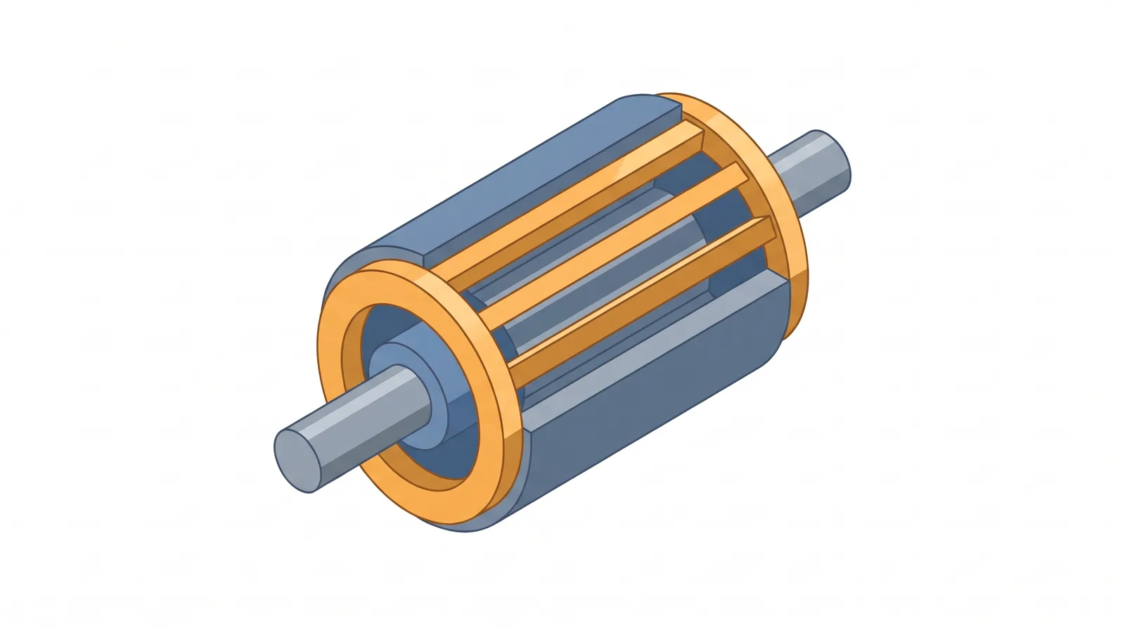
In an induction motor, the rotor field is induced by the stator field itself. The rotor conductors must be cut by the rotating field for a voltage to be induced in them, so a motoring rotor turns more slowly than the field. The FAA handbook spells out what happens if it did not: if the rotor turned at the same speed as the field, its conductors would not be cut by any lines of force, no EMF would be induced, no current could flow, and there would be no torque. The difference is called slip, expressed as a percentage of synchronous speed; the handbook's example of a rotor running 50 rpm below an 1,800 rpm field gives \( 50/1800 = 2.78 \) percent. The usual rotor is the squirrel cage: an iron core with heavy copper or aluminium bars in longitudinal slots, welded to a high-conductivity ring at each end.
In a synchronous motor, the torque does not depend on currents induced in the rotor. The rotor carries its own field, which locks to the rotating stator field and turns at exactly the same speed. If the load is too large, the rotor pulls out of synchronism with the field and no longer rotates with it: the motor is overloaded. The FAA handbook notes that the rotor field may come from a permanent magnet, or from an electromagnet energised from a DC source through slip rings, as in an alternator. In the permanent magnet synchronous motor (PMSM), magnets on the rotor create the field. The E-811 and the ENGINeUS100B1 both use permanent magnet motors; the E-811's is described in its data sheet as an axial flux synchronous permanent magnet motor. ORNL summarises the gain over the induction motor: no rotor bar losses, and no need for slip, because the motor is synchronous with the electrical speed.
| Feature | Induction motor | Permanent magnet synchronous motor |
|---|---|---|
| Source of the rotor field | Currents induced in the rotor bars | Magnets on the rotor |
| Rotor speed | Below synchronous speed (slip) | Exactly synchronous |
| Torque at synchronous speed | None | Its normal running condition |
| Rotor losses | Rotor bar \( I^2R \) losses | No rotor bar losses |
A synchronous machine brings one requirement the induction motor does not have. Torque is produced only when the stator field is placed correctly relative to the rotor's magnets, so the controller must know the rotor angle at every instant. The X-57 high-lift motor controller is "sensorless": it uses no encoder or other position feedback device and estimates angle and speed with an observer, and because those estimates are inaccurate at low speed it uses special algorithms to start and stop the motor. NASA's analysis uses a frame of reference, the d-q frame, that rotates with the rotor. For surface permanent magnet machines without rotor saliency, maximum torque per ampere is achieved with all the current in the torque-producing axis (q-axis) and none in the d-axis. Interior permanent magnet machines produce two torque components, magnet torque and reluctance torque; ORNL's illustration for a general PMSM, drawn at one example current magnitude, puts the maximum magnet torque at a current angle of 0 electrical degrees, the maximum reluctance torque at 45 and the maximum total torque at about 35, and ORNL adds that the best angle varies with conditions such as current magnitude and speed.
Flux in a machine can be worked out much like current in an electric circuit. NASA's design methods model a motor as a network of magnetic reluctances (resistances to flux) and magnetomotive force (MMF) sources, and solve for the flow of flux in the same way current is solved for; a coil's MMF is its number of turns times the current in each turn, \( NI \). Iron has a relative permeability orders of magnitude greater than that of air and of permanent magnet material, so in most of the circuit the iron can be treated as carrying flux almost freely, and the air gap and the magnets dominate the reluctance. The notable exceptions are saturated iron, such as stator tooth tips, which often saturate. NASA notes that the mechanical air gap of a motor is typically around 1 mm.
Because magnet material has a permeability similar to that of air, a magnet is part of the reluctance it has to drive flux through. Increasing magnet thickness raises the gap flux density, but the marginal gains decrease rapidly at larger thicknesses: each extra millimetre of magnet adds reluctance as well as MMF. The other limit is saturation. NASA's X-57 high-lift motor used Hiperco-50 electrical steel for its maximum flux density saturation point of 2.4 T, because steels with high saturation flux density let more flux flow through a smaller area of iron, which reduces mass. Saturation, hysteresis and reluctance in general are covered in Module 3.10.
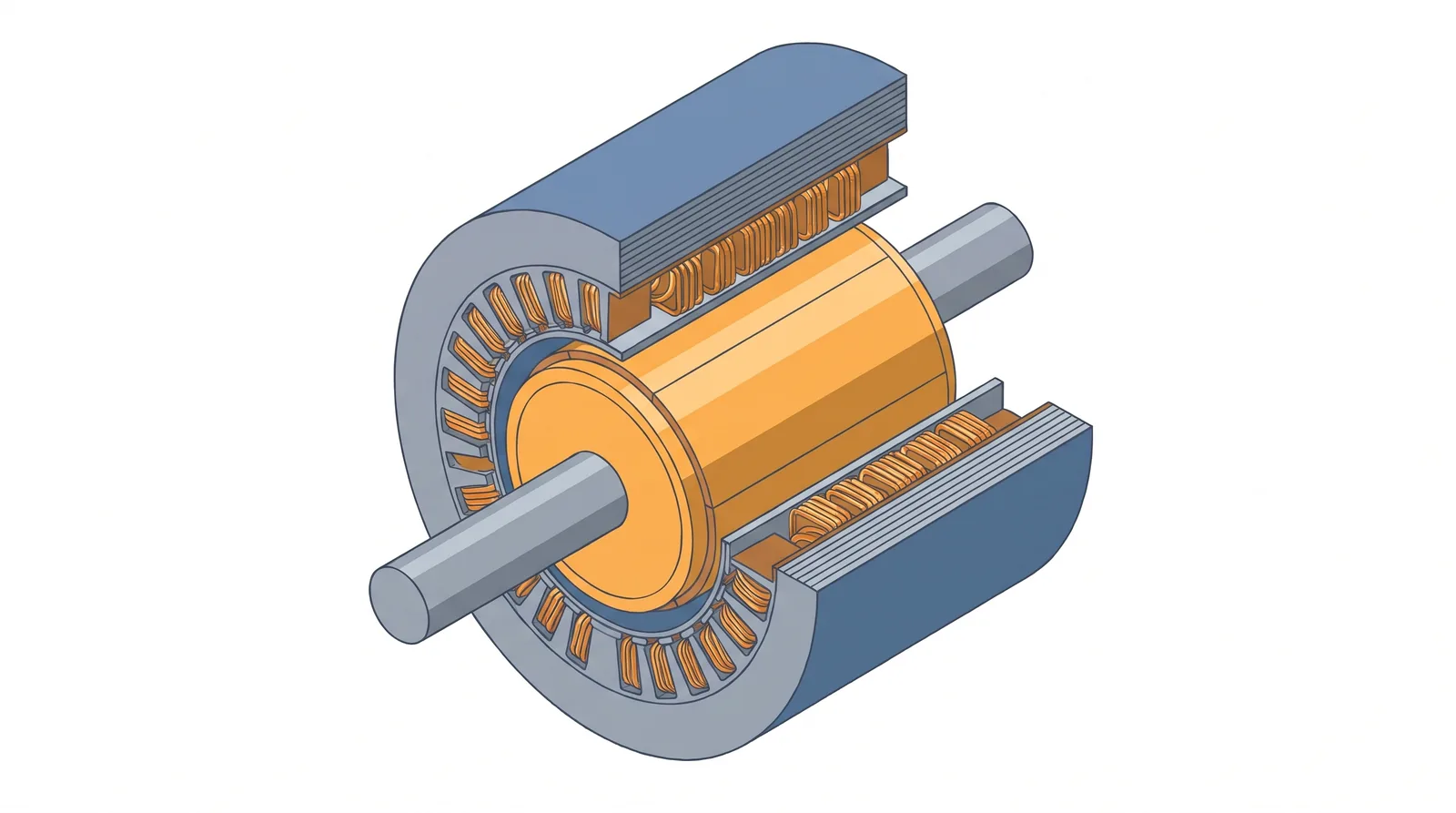
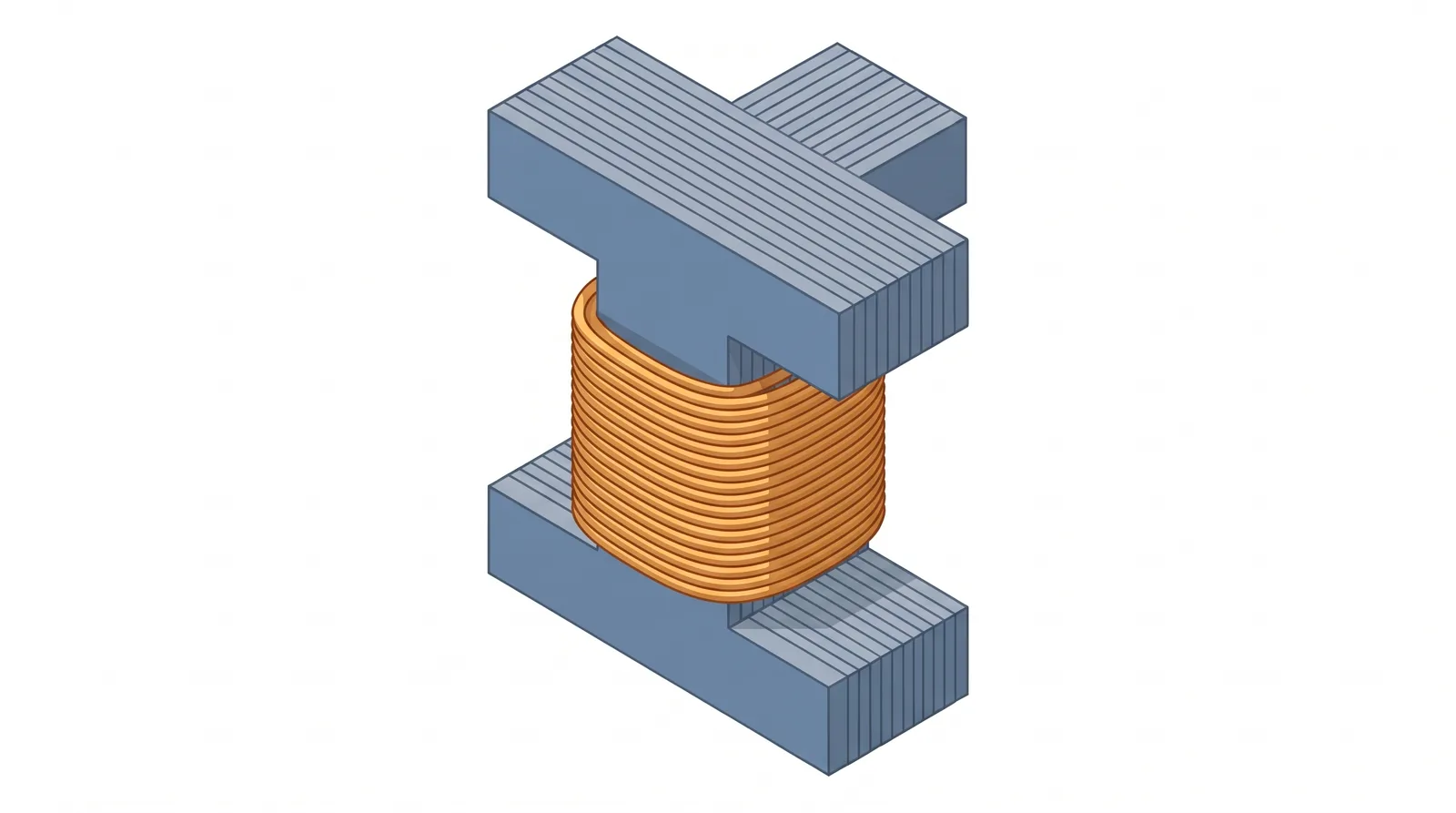
Iron that carries alternating flux heats up, and the FAA handbook divides these iron losses into hysteresis losses and eddy current losses. Eddy currents are induced in the core itself; they heat it and, if excessive, can damage the windings. The cure is a laminated core, made of thin sheets of iron electrically insulated from each other. The insulation between laminations has no effect on the magnetic circuit, but it breaks up the eddy-current paths, and the thinner the laminations, the more effectively this reduces eddy current losses. The figure below compares a solid core with a laminated one.
NASA's X-57 work puts numbers on it. Reducing the lamination thickness from 0.014 in to 0.006 in (about 0.36 mm to 0.15 mm) cut the stator loss from 286 W to 117.6 W, and even at 0.006 in the eddy currents still dominated, at 74.4 W against 43.4 W of hysteresis loss. NASA's design methods add that iron losses are typically the largest loss other than stator resistive losses, and that rotor iron loss is generally small in a synchronous permanent magnet machine, because most of the flux the rotor iron sees comes from its own magnets, which rotate with it.
Frequency is what makes iron loss grow with speed. One common expression for iron loss per unit volume, the Bertotti form given by NASA, separates the hysteresis, eddy and excess components:
\( f \) is the frequency of the magnetic field, \( B \) the peak flux density, and \( k_h \), \( k_c \), \( k_e \) and \( \beta \) are fitted coefficients for the steel. The middle term is the eddy-current loss. NASA notes that at higher frequencies the eddy term can be corrected to account for skin depth.
At a given peak flux density, doubling the frequency doubles the hysteresis term but multiplies the eddy-current term by four. Since electrical frequency rises with both speed and pole number (\( f = N_s p / 120 \)), high-speed, high-pole-count machines are where eddy losses bite hardest. ORNL's assessment of automotive traction motors makes the point about the extra eddy-current losses that fractional-slot concentrated windings can cause in the iron, the magnets and the windings: the problem tends to be most severe in high-speed machines (above 10,000 rpm) with a high pole count, "since the eddy currents scale as the square of the frequency", and the remedies include segmenting the rotor magnets, transposing (twisting) the stator windings and using thinner stator laminations.
Magnets conduct electricity too, so they carry eddy currents of their own. The X-57 high-lift motor's magnets were axially laminated, split into segments along the shaft, to reduce eddy current losses; with eight segments the magnet loss was approximately 15 W, or 3.5 percent of the motor's total losses. Magnet heating matters out of proportion to its size, because a hot magnet is a weaker magnet (thermal management, below).
Not all the flux a stator winding produces does useful work. NASA defines the winding factor as the fraction of the flux produced by a given stator winding that interacts with the rotor flux to produce torque; it expresses how well the winding layout matches the rotor's poles. It typically lies between 0.85 and 1, with distributed full-pitch windings at 0.95 to 1.00. A distributed winding lays each coil across several slots, and its stator has many more slots than the machine has poles (36 slots for 4 poles, for example). A concentrated winding is wound round individual stator teeth and belongs to designs whose slot count is close to their pole count. The X-57 high-lift motor is one, with 24 slots for its 20 poles: NASA notes that this combination of slots and poles requires concentrated windings, and that the fractional slot pitch they introduce decreases efficiency and torque compared with a distributed winding layout.
Slot and pole numbers also decide whether the magnetic forces on the rotor cancel. When a combination lacks symmetry, the radial pulls between rotor and stator do not balance, and a net side force acts on the rotor. NASA found that 21 slots and 20 poles would have given the X-57 motor a higher winding factor, but at the cost of an unbalanced magnetic pull of 169 N; the 24-slot, 20-pole design chosen reduced it to 1.7 N. A net radial magnetic force acts as a negative stiffness on the rotor and so lowers its critical speed, and faulted operation typically destroys the symmetry and generates relatively high radial forces. The regulators recognise the magnetic source of vibration: SC E-19 requires electromagnetic field excitation induced vibrations to be acceptable throughout the flight envelope and operating range, and the FAA's magniX conditions list electromagnetic among the sources of induced vibration the vibration survey must assess.
The previous sections end in the same place. Every loss, copper, iron, magnet, windage, bearing or switching, appears as heat in the hardware, and the magnets, the winding insulation, the bearings and the power semiconductors all have temperatures they must not exceed. NASA's design methods for aircraft permanent magnet machines state the conclusion without qualification: thermal performance is the primary constraint that limits the achievable specific power of a motor, and any motor sizing or design that neglects thermal modelling will yield a compromised or flawed solution. Magnet strength sets the torque per ampere and the supply voltage limits the speed, but how much current the windings can carry, and for how long, is decided by how fast the heat can be taken away; how hard the iron can be worked is capped by saturation and, at speed, by the heat its own losses make.
A combustion engine has a built-in heat disposal route. NASA's thermal analysis of the X-57 wingtip propulsion points out that traditional internal combustion engines may produce much more heat than electric components, but this waste heat is expelled through the exhaust. In an electric aircraft, temperature limits are a major concern in component design and the dissipation of heat is spread across the aircraft: batteries, power buses, motors and inverters all carry a thermal load, and that load has to be managed without excessive weight and drag. An electric engine has no exhaust stream, so its heat must be moved by air or liquid through heatsinks, cooling jackets or radiators to somewhere it can be released.
The heat is also made in small, separate places. NASA notes that inverter switches in particular are small, localised heat sources, with thermal limits in the 120 °C range for silicon carbide devices, and that the thermal resistance inside the switch (junction to case) and the contact resistance between switch and heatsink (case to sink) can be the dominant resistances in their heat path. A motor's losses are spread through its windings, stator iron, rotor and magnets, each with its own route out.
The FAA is blunt about the consequence. In both the magniX and the BETA special conditions it states that loss of cooling to an engine that operates using electrical technology can result in rapid overheating and abrupt engine failure, with critical consequences to safety. That is why the magniX conditions treat blockage of the cooling systems as a hazardous engine effect (the first section), and why they require that, where cooling is needed to satisfy the safety analysis, the cooling system's monitoring features and their use are documented in the installation manual. A separate condition requires instrumentation that lets the flight crew monitor the engine cooling system unless evidence shows it is not needed (for example, that other instruments give adequate warning). SC E-19 requires the cooling system to ensure adequate cooling in all flight attitudes and atmospheric conditions in which the EHPS is expected to operate, and all approved coolants and additives to be declared in the instructions for installation and operation.
In both the E-811 and the ENGINeUS100B1 the power electronics have the least room: their EASA data sheets set lower temperature limits for the power electronics than for the motor. The E-811's maximum motor temperature at MCP and MTOP is 110 °C and its maximum controller temperature 70 °C; the ENGINeUS100B1's, at its take-off and maximum continuous ratings, are 185 °C for the motor and 80 °C for the power electronics. The E-811's motor and controller are liquid-cooled, with the coolant entering at the power electronics and leaving at the motor, so the controller sees the coolest coolant. The data sheet sets a maximum coolant temperature of 60 °C at the controller inlet and a minimum coolant flow of 5.5 l/min. Combining those E-811 figures, the controller's temperature limit is only \( 70 - 60 = 10 \) °C above the hottest coolant permitted at its inlet. The coolant itself is not part of the type design, but a mixture of 50 percent water and 50 percent automotive-grade G12+ glycol is requested.
In the Velis Electro, which uses the E-811, the Pilot's Operating Handbook shows what happens when the engine coolant stops flowing. The motor and the power controller share one liquid-cooling system, with a radiator and one electrically driven pump, while the batteries have a separate liquid-cooling system with its own radiator and two pumps. If the engine coolant pump fails, the handbook warns that engine temperatures rise immediately as power is applied, and that the power controller temperature rises faster than the motor temperature and within a few seconds causes the controller to shut down, with total loss of power at most useful power settings. Engine coolant pump failure is one of the handbook's memory items, emergency procedures that require immediate reaction by the pilot. Being first in the coolant flow protects the controller only while the coolant is moving.
NASA models heat flow inside a machine with a thermal resistance network, the thermal twin of the magnetic circuit in the previous section. The heat that flows along a path equals the temperature difference across the path divided by the path's thermal resistance. Temperature difference plays the part of voltage, heat flow the part of current, and thermal resistance the part of electrical resistance; resistances in series add, exactly as in a DC circuit.
\( Q \) in watts, \( \Delta T \) in kelvin (or °C of difference), \( R_{th} \) in kelvin per watt. As an illustration, 250 W crossing a path of 0.2 K/W needs a 50 K temperature difference; halve the resistance and the same heat crosses with 25 K.
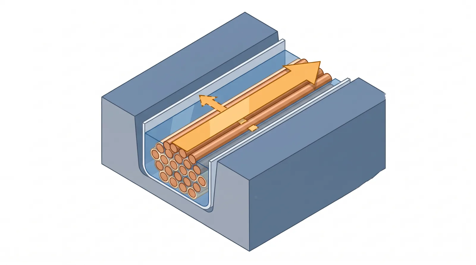
The stubborn part of the path is usually the winding. NASA notes that the stator iron and the stator windings are typically composites of metal, polymer insulation and epoxy, whose thermal conductivities can be approximated by the rule of mixtures. For windings of copper, polymer insulators and epoxy, the thermal conductivity along the winding path is typically 100 to 200 W/(m K), but in the plane perpendicular to it only 0.4 to 3.0 W/(m K), depending on the slot fill and on the thermal conductivity of the insulation and the epoxy. Heat travels roughly 30 to 500 times more easily along the conductors than across the winding. The copper itself conducts heat equally well in every direction; the difference comes from the layers of insulation and resin between the strands, which heat must cross one after another when it leaves the winding sideways. Between the winding and the iron there is usually a slot liner as well, 0.05 to 0.76 mm thick, and aromatic polyamide paper, a common liner material, has a thermal conductivity of only about 0.12 W/(m K). The insulation that keeps current inside the copper also keeps heat inside it.
Moving the heat costs energy too. NASA notes that coolant flow losses directly heat the fluid and so reduce the effectiveness of the cooling, and add pump mass and wasted energy, and that laminar flow in a fine-finned heatsink or in direct stator cooling slots will generally be enough to cool a motor while keeping those flow losses small.
NASA's X-57 high-lift motor shows a typical distribution. The majority of losses originate from the coils and the stator, and the converged steady-state analysis gave the following:
| Component (X-57 high-lift motor) | Temperature | Loss |
|---|---|---|
| Windings | 129 °C | 253.8 W |
| Stator | 128 °C | 117.6 W |
| Magnets | 90 °C | 15.0 W |
| Rotor | 78 °C | 3.85 W |
The windings make the most heat and run hottest, the stator iron is close behind, and the rotor and magnets make little heat of their own. Getting heat out of the rotor is a different problem, because the rotor spins on the other side of the air gap from the cooled stator. NASA's design methods state that convection inside the rotor cavity is typically the primary source of rotor cooling, and draw two conclusions about magnet temperature that depend on how the motor is used:
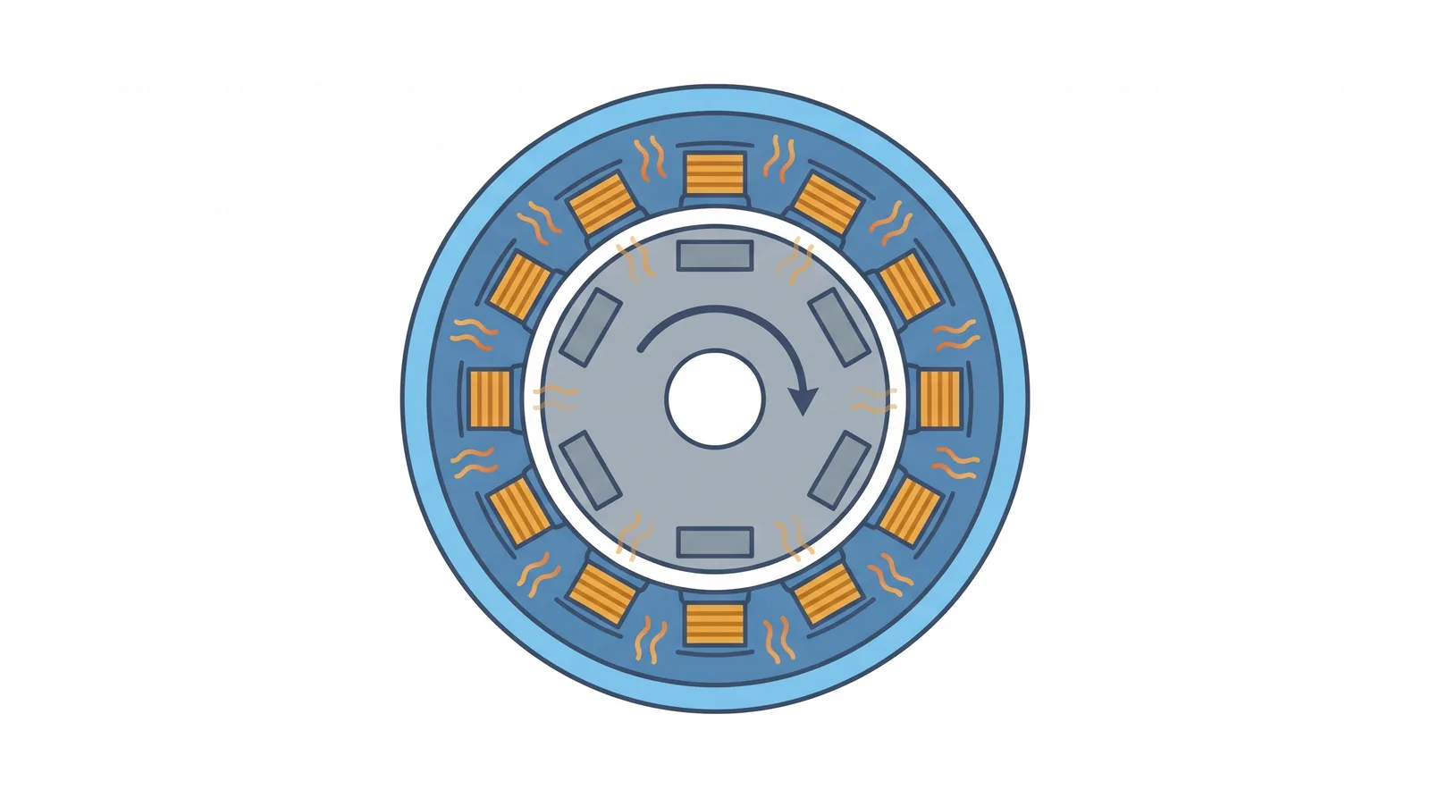
Magnet temperature matters because heat weakens magnets. In the X-57 analysis, the remanent flux density of the NdFeB magnets fell from the nominal 1.39 T at 20 °C to 1.273 T at 90 °C, a loss of about 8 percent (the torque requirement was still met). Less flux means less torque per ampere, so the controller needs more current for the same torque, which makes more copper loss. An ORNL assessment adds the more serious risk: elevated temperature reduces a magnet's coercivity, its resistance to demagnetisation, and at high enough temperatures this makes the magnet much more vulnerable to irreversible demagnetisation. Ferrite magnets are the exception, losing coercivity when they get colder. The copper suffers too: NASA notes that copper resistivity varies with temperature and gives a coefficient of 0.00393 per °C from its 20 °C value. A winding 100 °C above 20 °C therefore has about 39 percent more resistance, and makes about 39 percent more \( I^2R \) loss at the same current. Both effects push the same way: a hotter motor makes more heat for the same output.
The E-811 and the ENGINeUS100B1 take opposite approaches. The E-811 is liquid-cooled, motor and controller on one coolant flow, as described above. The ENGINeUS100B1 is air-cooled: its heatsinks and fins are open to external airflow provided by propeller rotation and by airspeed dynamic pressure, and the minimum airflow to be provided is specified in the engine installation and operating manual. Either way, the cooling is part of the installation, not only of the engine.
Passive air cooling works only when the air moves. NASA tested the X-57 high-lift motor controller on a water-cooled cold plate in the laboratory, because without the propeller and the extra air movement of a moving aeroplane it would have been insufficiently cooled. For the passively cooled X-57 high-lift motor, the worst thermal case was the static pre-flight run-up, 4,400 rpm for 30 seconds, because cooling is minimal while input power is high. A ground run is therefore a thermal event in its own right on such a design.
Cooling paths can also couple components together. In the X-57 cruise nacelle, the inverter fin row may be cooled by exhaust air from the motor heatsink, so the air passes through the motor first and the inverter second. NASA warns that any significant flow restriction through the inverter has a cascading effect: lower flow rates, therefore higher exhaust temperatures from the motor, making it more likely that both the motor and the inverter will overheat. A blockage at one end of a series cooling path heats everything on it. The figure below sets this path beside the E-811's coolant path.
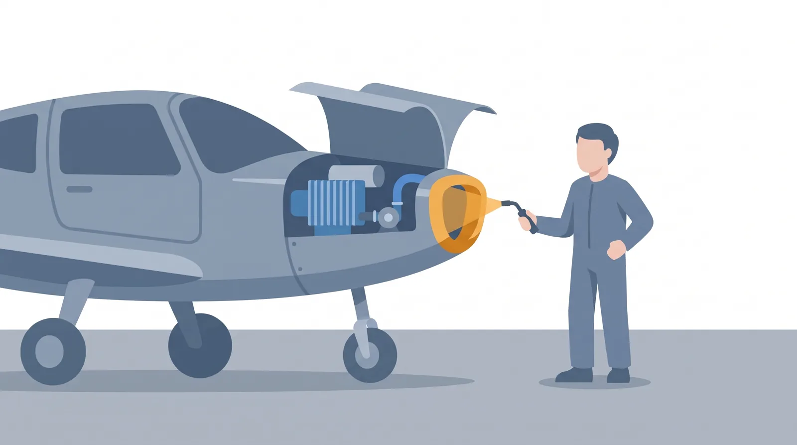
EASA's list of practical tasks for electric power plants includes inspecting cooling ducts, airflow paths and cowling integrity, adjusting cooling inlet and outlet shutters where they are installed, and checking the operation of fans or coolant pumps. In the magniX rulemaking a commenter warned that ferromagnetic debris could collect in air-cooled or coolant passages, because the magnets attract it; the FAA's view was that magnetic debris in a liquid cooling system would likely be a consequence of an engine failure or of inadequate maintenance. Keeping the cooling path clear, intact and flowing is part of keeping the engine within its limits.
Temperature does not jump to its final value; it climbs as the parts store heat, at a rate set by the gap between the heat made and the heat removed. So a motor can deliver more than its continuous power for a limited time, until its hottest part reaches its limit. ORNL's measurements on the 2010 Toyota Prius motor (an automotive machine, cooled by oil circulation and an ethylene-glycol loop) show how strongly the time available depends on two numbers, the temperature limit chosen and the coolant temperature:
Certified ratings are built on the same physics. In SC E-19's definitions, rated maximum continuous power is power for periods of unrestricted duration, and the E-811 data sheet shows the same pattern: its maximum take-off power of 57.6 kW is limited to 90 seconds, while no time limit is attached to its maximum continuous power of 49.2 kW. The way ratings, durations and temperature limits are set is covered in engine performance (18.2).
Temperature limits are not only about the next five minutes; they also decide how long the engine lasts. The first section noted that winding insulation and bearings are the dominant causes of motor failure, and both age with heat.
For industrial motors, the US DOE motor guide observes that motors which run hotter tend to have shorter lives, because failure often comes from oxidation and thermal degradation of the insulating materials, and quotes an often-stated rule of thumb: the service life expectancy of winding insulation is halved for each 10 °C increase in operating temperature. It adds that real insulation life is also affected by the number of starts, voltage surges and sags, undervoltage operation and voltage unbalance. Treat the halving rule as what it is, a rule of thumb for industrial motors, not a law for aircraft engines.
An industrial motor's winding runs 20 °C hotter than intended. Under the DOE rule of thumb that is two 10 °C steps, so its expected insulation life becomes \( \left(\tfrac{1}{2}\right)^2 = \tfrac{1}{4} \) of the original. Running 10 °C cooler would, on the same rule, double it.
NASA's work on aircraft motor insulation refines the picture in three ways. First, thermal stresses degrade insulation gradually by accelerating chemical reactions, traditionally modelled by Arrhenius's law, but that model has flaws: degradation occurs only at temperatures high enough for the dominant reactions to take place, and several reactions may act at once. Second, in an urban air mobility mission study, the high-power, short-duration hover and climb segments dominated the thermal-chemical ageing of the insulation, while the long, low-power cruise contributed only minimally; this is the square-law heat described under power and efficiency showing up as lost life. Third, for aircraft motors, thermo-mechanical stress cycles of the winding insulation, each heating to peak temperature and cooling again, are potentially more limiting than the thermo-chemical ageing on which the usual insulation thermal classes are based.
Oxygen drives much of the chemistry. NASA notes that in the absence of oxygen, as in direct liquid-cooled stators or inert gas environments, the thermo-chemical life of the insulation is driven by a reaction other than oxidation, and cites tests in which polyimide films at 360 °C degraded completely in hundreds of hours in air, while films in nitrogen showed no notable loss of thickness after 1,000 hours.
Bearings follow the same pattern. The DOE guide notes that a motor's grease life varies with temperature: as bearing temperature increases, the motor must be regreased more frequently to prevent premature bearing failure. Bearings, shafts and their lubrication are part of engine construction (18.3); the principle for now is that, other things being equal, a cooler engine is a longer-lived one.
Printing is not available
Please view study notes online at part66online.com
Sections
9,500+ pages across all 17 EASA Part-66 modules, written paragraph by paragraph against the syllabus — with worked examples, formulas, diagrams and exam tips.
A failed module costs you a re-sit fee, weeks of revision and a later licence. Don’t let one topic be the reason.
Just €5.88 a module · no auto-renewal
Just €17.65 a module · yours to keep
Download link sent to your email
We use essential cookies to keep you signed in, plus anonymous analytics to understand how the site is used. Cookie-based analytics is set only with your consent. See our Privacy & Cookie Policy.