Module 17 — Propeller
17.1 — Fundamentals
Introduction
A propeller is an aerodynamic device that converts the rotary power (torque) produced by an engine into thrust — a forward-acting force that propels the aircraft through the air. Although jet engines dominate large transport aircraft, propellers remain essential on turboprops, piston-engined aircraft, and many modern regional airliners. Every EASA Part 66 engineer must thoroughly understand propeller theory, because the propeller is the final link in the powerplant chain — if it is inefficient, damaged, or incorrectly set, no amount of engine power will produce adequate performance.
A propeller blade is, in every meaningful sense, a rotating wing. It has an aerofoil cross-section, generates lift (which we call thrust when directed forward), produces drag, and is subject to the same aerodynamic principles that govern a wing. The key difference is that while a wing translates through the air, a propeller blade rotates and translates simultaneously, giving each blade element a unique combination of rotational velocity and forward velocity.
Blade Element Theory
Blade element theory is the fundamental method for analysing propeller performance. Rather than treating the blade as a single unit, blade element theory divides each blade into a series of small independent sections (elements), each at a different distance from the hub. Each element is then analysed as a tiny aerofoil operating in its own local airflow.
Why is this necessary? Because conditions vary dramatically along the blade:
- Near the hub — the rotational speed is low (small radius × RPM), so the element "sees" a relatively slow airflow
- Near the tip — the rotational speed is very high (large radius × RPM), so the element "sees" a much faster airflow
- At each station, the blade angle, angle of attack, lift, drag, and local efficiency are all different
Rotational velocity at any blade station:
\[ V_{rot} = 2\pi r n \]
Where: \( r \) = distance from hub centre (m), \( n \) = rotational speed (rev/s)
At the tip of a 2 m diameter propeller spinning at 2,400 RPM (40 rev/s):
\[ V_{rot} = 2\pi \times 1.0 \times 40 = 251 \text{ m/s} \approx 905 \text{ km/h} \]
This is approaching the speed of sound — which is why propeller tips can go supersonic, causing noise and efficiency loss.
Blade element theory sums (integrates) the thrust and torque contributions of every element along the blade span to calculate the total propeller thrust and the power required to turn it. The key insight is that each element must operate at an efficient angle of attack, which is why propeller blades are twisted — the blade angle is large near the hub and small near the tip.
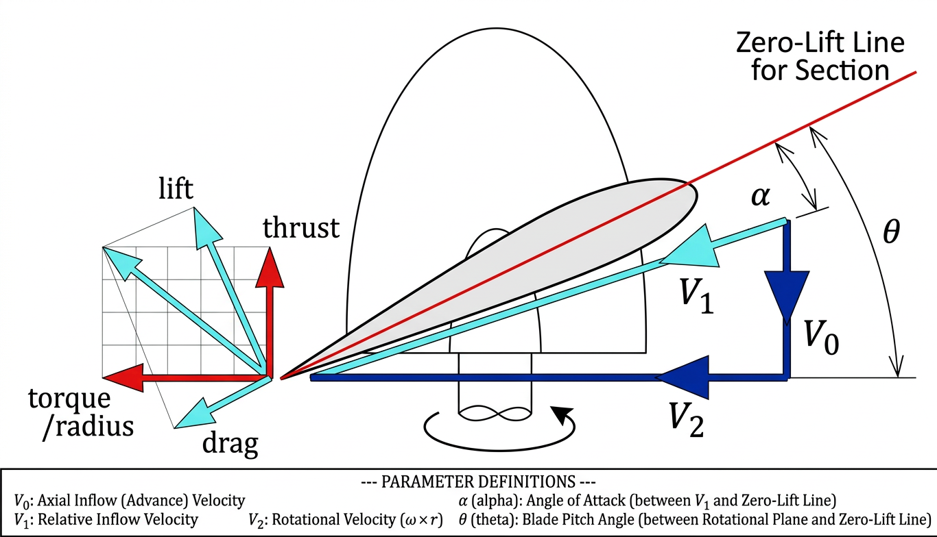
Key Relationship: β = φ + α
The diagram above shows the fundamental angular relationship for any blade element:
Blade angle = Helix angle + Angle of attack
\[ \beta = \varphi + \alpha \]
- β (beta) — Blade angle: the angle between the blade chord line and the plane of rotation. This is a fixed geometric property of the blade at any given station (unless the propeller has variable pitch).
- φ (phi) — Helix angle: the angle between the relative airflow (RAF) and the plane of rotation. This changes with forward speed and rotational speed.
- α (alpha) — Angle of attack: the angle between the chord line and the relative airflow. This determines how much lift (thrust) the blade element produces.
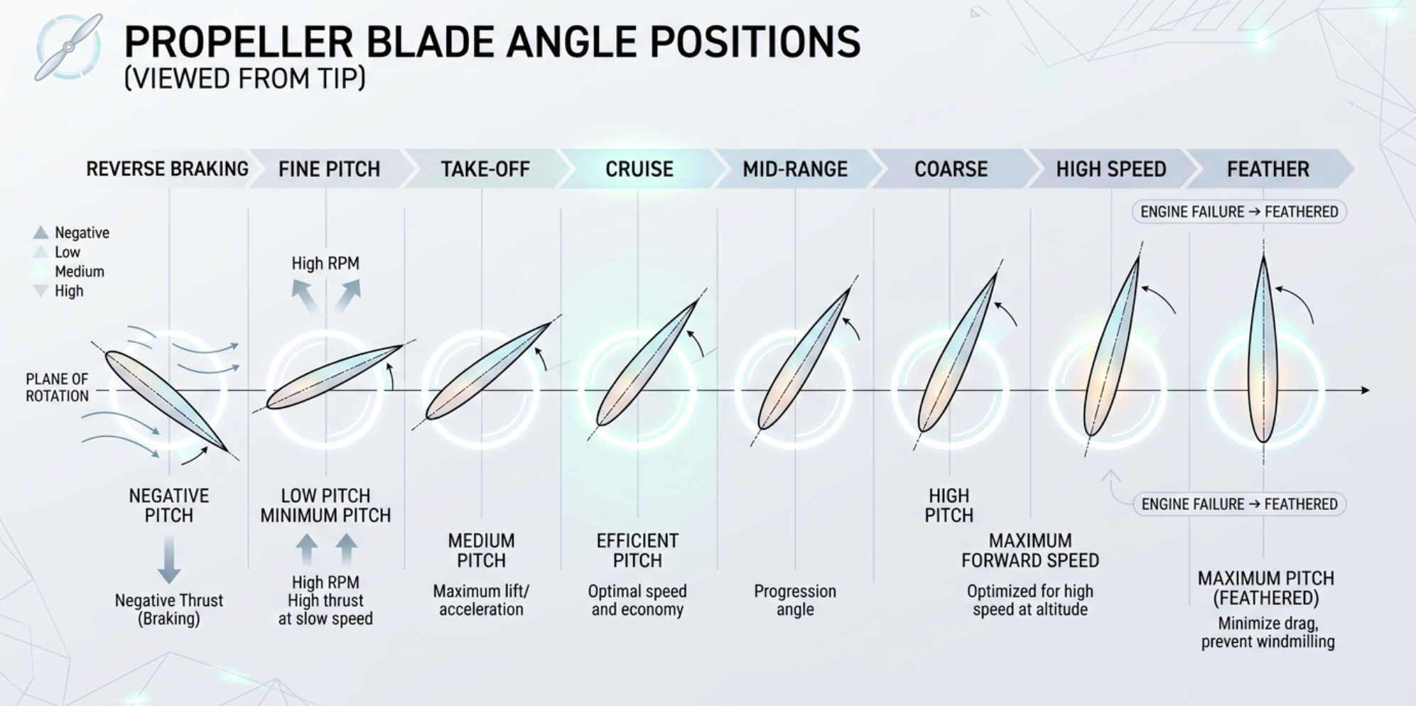
Blade Angle — High, Low, and Reverse
High Blade Angle (Coarse Pitch)
A high blade angle (also called coarse pitch) means the blade chord is angled steeply relative to the plane of rotation. The blade takes a bigger "bite" of air per revolution — like a screw with a steep thread. This is analogous to a high gear in a car.
- Used during cruise and high-speed flight
- Each revolution moves the aircraft a greater distance through the air
- Requires more engine torque (more load on the engine)
- Lower RPM for a given power setting → better fuel efficiency at speed
- Inefficient at low speed because the angle of attack becomes too large, risking blade stall
Low Blade Angle (Fine Pitch)
A low blade angle (also called fine pitch) means the blade chord is nearly flat relative to the plane of rotation. The blade takes a small bite of air per revolution — like a shallow screw thread. This is analogous to a low gear in a car.
- Used during take-off, climb, and low-speed flight
- Allows the engine to develop high RPM without excessive load
- Produces maximum thrust at low forward speeds
- Inefficient at high speed because the blade merely "slices" the air with little forward advance per revolution
Reverse Angle (Reverse Pitch)
In reverse pitch, the blade angle is rotated past the flat (zero-thrust) position so that the leading edge now faces aft. The propeller produces reverse thrust — a braking force directed forward (opposing the aircraft's motion). This is used:
- On the ground after landing to shorten the landing roll
- For ground manoeuvring — allows the aircraft to taxi backwards or turn sharply
- In some turboprop aircraft, as a primary braking method on short runways
Exam caution: Do not confuse reverse pitch with feathering. Reverse pitch produces reverse thrust for braking. Feathering aligns the blade with the airflow (≈ 90° blade angle) to minimise drag after an engine failure. They are opposite ends of the blade angle range.
Angle of Attack
The angle of attack (α) of a propeller blade element is the angle between the element's chord line and the relative airflow (RAF) — the resultant of the rotational velocity and the aircraft's forward velocity. This is exactly the same concept as the angle of attack of a wing, applied to each small section of the blade.
The angle of attack determines:
- How much lift (thrust) the blade element produces
- How much drag (torque resistance) it creates
- Whether the element operates efficiently or is stalled
As forward speed increases (at constant RPM and blade angle), the helix angle φ increases, which reduces the angle of attack (since β = φ + α and β is fixed). Less lift is produced per element → the propeller becomes less efficient. Conversely, as forward speed decreases, α increases and could lead to blade element stall at very low speeds.
Key insight: This is precisely why variable-pitch propellers exist — by adjusting β (blade angle) to match the changing flight conditions, the propeller can maintain an optimal angle of attack across a wide range of airspeeds. A fixed-pitch propeller can only be optimised for ONE speed.
Rotational Speed
Rotational speed (measured in RPM — revolutions per minute, or rev/s) is how fast the propeller turns. It is directly controlled by the engine throttle (on fixed-pitch propellers) or by the propeller governor (on constant-speed propellers).
Rotational speed affects propeller performance in several critical ways:
| Effect | Detail |
|---|---|
| Thrust | Higher RPM = more air accelerated = more thrust (up to a point) |
| Tip speed | Higher RPM increases tip speed. If tip speed approaches or exceeds Mach 1, compressibility effects cause severe efficiency loss, noise, and vibration. |
| Blade AoA | At constant forward speed and fixed blade angle: increasing RPM decreases the helix angle φ, which increases AoA α. Too high → blade stall. |
| Centrifugal loads | Centrifugal force on each blade increases with the square of RPM. Structural limits set the maximum permissible RPM. |
| Engine stress | Exceeding maximum RPM (overspeed) can cause catastrophic engine or gearbox failure. |
Propeller Slip
Propeller slip is the difference between the geometric pitch distance (the theoretical distance the propeller would advance in one revolution if it were screwing through a solid) and the effective pitch distance (the actual distance it advances through the air).
Slip:
\[ \text{Slip} = \text{Geometric pitch} - \text{Effective pitch} \]
\[ \text{Slip } (\%) = \frac{\text{Geometric pitch} - \text{Effective pitch}}{\text{Geometric pitch}} \times 100 \]
Slip occurs because air is a fluid, not a solid. A screw in wood advances its full pitch distance each revolution because wood is rigid. Air, however, yields and accelerates — some of the propeller's energy goes into accelerating the air rearward rather than advancing the aircraft forward. Typical propeller slip ranges from 10% to 30% depending on conditions.
Example: A propeller has a geometric pitch of 2.0 m. At a given airspeed and RPM, the aircraft advances 1.5 m per revolution.
\[ \text{Slip} = 2.0 - 1.5 = 0.5 \text{ m} \]
\[ \text{Slip } \% = \frac{0.5}{2.0} \times 100 = 25\% \]
Slip is not wasted energy — it is the mechanism by which thrust is produced. Without slip, there would be no acceleration of air and no thrust (just as a wing at zero angle of attack produces no lift). However, excessive slip indicates low propeller efficiency.
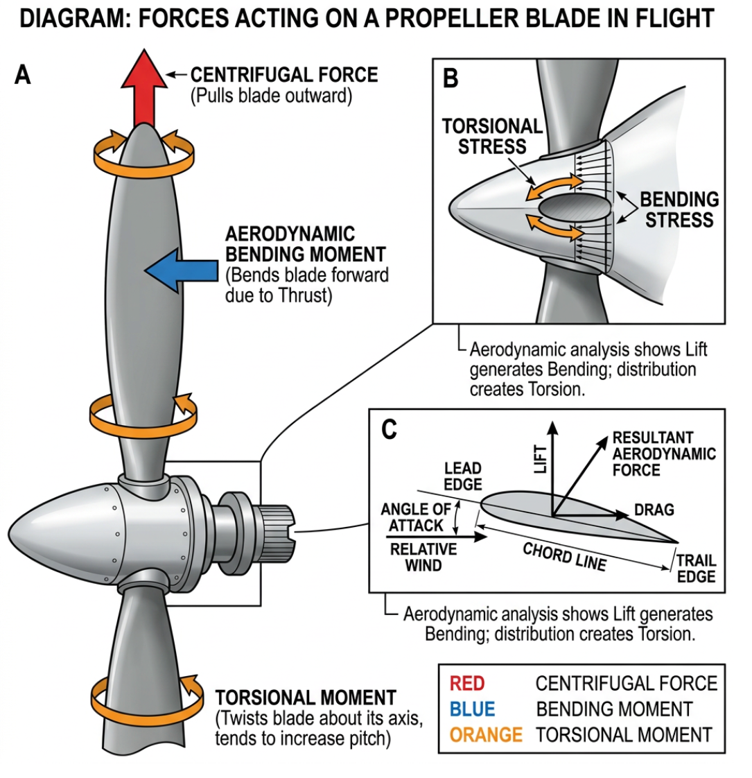
Forces Acting on a Propeller Blade
Every rotating propeller blade is subject to several simultaneous forces. Understanding these is critical for appreciating blade design, pitch control, and structural requirements.
1. Centrifugal Force (Centrifugal Twisting Moment — CTM)
Centrifugal force acts on every particle of the blade, pulling it radially outward from the axis of rotation. This is the dominant structural load — it tries to pull the blade out of the hub. On a large turboprop at full RPM, the centrifugal load on each blade can exceed 20 tonnes.
Centrifugal force also creates the Centrifugal Twisting Moment (CTM). Because the centre of mass of each blade element does not coincide with the pitch-change axis, centrifugal force creates a torque that tends to twist the blade toward fine pitch (low blade angle). This is because centrifugal force tries to align all the mass in the plane of rotation, which means reducing the blade angle.
Centrifugal force on a blade element:
\[ F_c = m \omega^2 r \]
Where: \( m \) = mass of the element, \( \omega \) = angular velocity (rad/s), \( r \) = radius from the axis
Since \( \omega = 2\pi n \), centrifugal force increases with the square of RPM.
2. Aerodynamic Force (Aerodynamic Twisting Moment — ATM)
The aerodynamic force is the resultant of lift and drag acting on each blade element. This force acts through the centre of pressure of the blade section. Because the centre of pressure is typically ahead of (forward of) the pitch-change axis, the aerodynamic force creates the Aerodynamic Twisting Moment (ATM), which tends to twist the blade toward coarse pitch (high blade angle).
The ATM opposes the CTM. In most propeller designs:
- CTM > ATM — the net tendency is toward fine pitch
- The pitch control system must therefore work against the CTM to increase blade angle (toward coarse/feather)
- This is an important safety consideration — if the pitch control fails, the blade will tend toward fine pitch, which at high speed means engine overspeed
3. Thrust Bending Force
The thrust produced by each blade element acts in the forward direction (parallel to the aircraft's flight path). Because the blade is attached at the hub and the thrust loads are distributed along its span, a bending moment is created that tries to bend the blade forward. The blade root must be strong enough to resist this bending.
4. Torque Bending Force
As the engine drives the propeller, aerodynamic drag on each blade element resists the rotation. This creates a torque bending force that tries to bend the blade backward (against the direction of rotation). This opposes the thrust bending force but acts in a different plane.
5. Vibratory Forces
Cyclic variations in airflow (e.g., due to the aircraft's angle of attack causing the descending blade to see a different angle than the ascending blade) produce once-per-revolution (1P) vibratory forces. Higher-order vibrations (2P, 3P, etc.) also occur. These vibratory forces can cause fatigue cracking if not controlled.
Torque
Torque is the rotational force (turning moment) that the engine must supply to keep the propeller turning against aerodynamic drag. It is the "resistance" the propeller presents to the engine.
Relationship between power, torque, and RPM:
\[ P = 2\pi n Q \]
Where: \( P \) = shaft power (W), \( n \) = rotational speed (rev/s), \( Q \) = torque (N·m)
Rearranging: \( Q = \frac{P}{2\pi n} \)
This shows that for a given power, reducing RPM increases torque — this is why turboprop engines use reduction gearboxes. A turbine spinning at 30,000 RPM produces relatively low torque; the gearbox converts this to ~1,200 RPM at much higher torque.
Engine torque must match propeller torque at the selected RPM. If engine torque exceeds propeller torque, the propeller accelerates. If propeller torque exceeds engine torque, the propeller decelerates. The constant-speed propeller governor works to maintain this balance by adjusting blade angle.
Relative Airflow on Blade Angle of Attack
The relative airflow (RAF) striking any blade element is the vector sum of two perpendicular velocities:
- Rotational velocity — tangential to the circle of rotation, in the plane of rotation. This is \( V_{rot} = 2\pi rn \), where \( r \) is the blade station radius.
- Forward velocity (TAS) — the aircraft's true airspeed, perpendicular to the plane of rotation.
The resultant RAF approaches the blade element from below and ahead. The angle this resultant makes with the plane of rotation is the helix angle (φ):
\[ \tan\varphi = \frac{V_{TAS}}{2\pi r n} \]
The helix angle is small near the tip (because rotational velocity is large) and large near the hub (because rotational velocity is small).
Since the blade angle β is fixed at each station (for a given pitch setting), and β = φ + α, the angle of attack α at each element depends on the helix angle:
\[ \alpha = \beta - \varphi \]
This means:
- Increasing forward speed (at constant RPM) → larger φ → smaller α → less thrust
- Decreasing forward speed (at constant RPM) → smaller φ → larger α → more thrust (up to stall)
- Increasing RPM (at constant TAS) → smaller φ → larger α → more thrust
Why propeller blades are twisted: Because rotational velocity increases with radius, the helix angle φ is large at the root and small at the tip. To maintain a roughly constant (efficient) angle of attack α along the entire blade, the blade angle β must be large at the root and small at the tip. This built-in twist is called geometric twist or washout.
Vibration and Resonance
Propeller vibration is a critical concern for both structural integrity and crew/passenger comfort. Vibration originates from several sources:
Sources of Propeller Vibration
| Source | Description | Frequency |
|---|---|---|
| Mass imbalance | Unequal mass distribution between blades (manufacturing tolerance, damage, repair, ice). Creates 1-per-revolution (1P) vibration. | 1P (once per rev) |
| Aerodynamic imbalance | Unequal thrust between blades due to differences in blade angle, aerofoil profile, or surface condition. Creates 1P vibration. | 1P |
| Asymmetric airflow | When the aircraft is at an angle of attack, the descending blade has a higher AoA than the ascending blade. Creates cyclic 1P loading. | 1P |
| Engine firing impulses | On piston engines, each cylinder fires in sequence, creating torque pulses that excite the propeller. A 4-cylinder engine at 2,400 RPM creates pulses at 80 Hz. | Varies with engine type |
| Propeller wake/P-factor | Interaction between the propeller slipstream and aircraft structure (wing, nacelle) creates periodic forces. | Blade-passing frequency |
Resonance
Resonance occurs when the frequency of an exciting force matches a natural frequency of the propeller blade (or the engine/airframe system). At resonance, vibration amplitude increases dramatically — potentially to the point of structural failure.
Every propeller blade has multiple natural frequencies corresponding to different modes of vibration:
- First flap mode — the blade bends forward and backward (like a diving board)
- First edgewise mode — the blade bends in the plane of rotation (side to side)
- Torsional mode — the blade twists about its spanwise axis
- Higher-order modes — more complex shapes with multiple nodes
The operating RPM range of the propeller must be chosen to avoid critical resonance speeds. If a resonance cannot be avoided, it must pass through quickly (hence "restricted RPM ranges" in some aircraft flight manuals — RPM ranges where you must not operate continuously).
Operational note: Some aircraft have yellow-arc RPM ranges on the tachometer that indicate resonance danger zones. These ranges must be transited quickly and never used for continuous operation. Operating in a resonance range can lead to fatigue cracking and ultimately blade failure.
Propeller Efficiency
Propeller efficiency (η) is the ratio of useful thrust power to the shaft power delivered by the engine:
\[ \eta = \frac{\text{Thrust} \times V_{TAS}}{\text{Shaft Power}} = \frac{T \times V}{P} \]
Typical maximum propeller efficiency: 80–88% for well-designed propellers at their optimal operating point.
Propeller efficiency varies with advance ratio (J), which is the ratio of forward speed to the product of RPM and diameter:
\[ J = \frac{V}{nD} \]
At J = 0 (static, zero forward speed), efficiency is zero — thrust is produced but no useful work is done (no distance covered). As J increases, efficiency rises to a peak and then falls as the propeller loses its ability to produce thrust at high forward speeds. A variable-pitch propeller maintains high efficiency over a wider range of J by adjusting blade angle.
Printing is not available
Please view study notes online at part66online.com