Module 16 — Piston Engine
16.1 — Fundamentals
Introduction
The piston engine (reciprocating engine) converts the chemical energy in aviation fuel into mechanical energy through a repeated cycle of combustion events inside cylinders. Despite being one of the oldest forms of aircraft powerplant, piston engines remain the dominant choice for light aircraft, trainers, and many general aviation types. Every Part 66 engineer working on these aircraft must have a thorough understanding of piston engine theory.
Operating Principles
The Four-Stroke (Otto) Cycle
The vast majority of aircraft piston engines use the four-stroke Otto cycle. Each cylinder completes four distinct strokes (two complete crankshaft revolutions = 720°) to produce one power event:
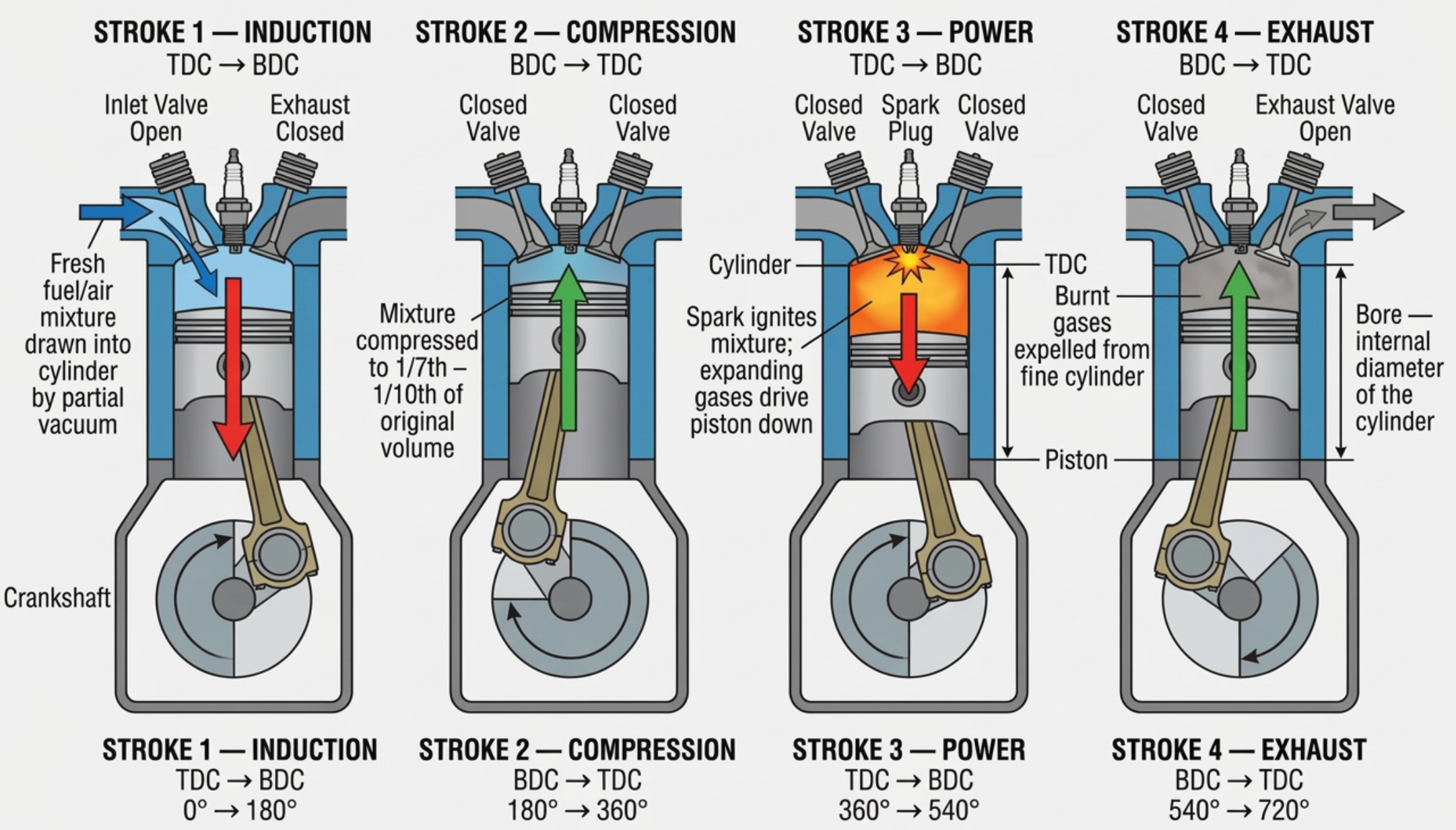
Memory aid — "Suck, Squeeze, Bang, Blow": This classic mnemonic summarises the four strokes: Induction (suck mixture in), Compression (squeeze it), Power (bang — ignition and expansion), Exhaust (blow gases out).
Stroke-by-Stroke Detail
| Stroke | Piston | Inlet Valve | Exhaust Valve | Crankshaft | Action |
|---|---|---|---|---|---|
| 1 — Induction | TDC → BDC | Open | Closed | 0° → 180° | Fresh fuel/air mixture drawn into cylinder by partial vacuum |
| 2 — Compression | BDC → TDC | Closed | Closed | 180° → 360° | Mixture compressed to 1/7th – 1/10th of original volume |
| 3 — Power | TDC → BDC | Closed | Closed | 360° → 540° | Spark ignites mixture; expanding gases drive piston down |
| 4 — Exhaust | BDC → TDC | Closed | Open | 540° → 720° | Burnt gases expelled from cylinder |
Key terms:
- TDC — Top Dead Centre: piston at highest point in cylinder
- BDC — Bottom Dead Centre: piston at lowest point in cylinder
- Stroke — distance between TDC and BDC
- Bore — internal diameter of the cylinder
The Two-Stroke Cycle
In a two-stroke engine, the cycle completes in just two strokes (one crankshaft revolution = 360°). The piston itself acts as a valve, covering and uncovering ports in the cylinder wall:
- Stroke 1 (upward): Piston compresses mixture above while drawing fresh charge into the crankcase below
- Stroke 2 (downward): Combustion drives piston down; near BDC, exhaust port uncovered, then transfer port admits fresh mixture from crankcase
Two-stroke engines have a higher power-to-weight ratio (one power stroke per revolution vs. one per two revolutions), but they are less fuel-efficient and produce more emissions. They are rarely used in certified aircraft but appear in some ultralight and microlight types.
The Diesel (Compression Ignition) Cycle
In a diesel cycle engine, there is no spark plug. Air alone is compressed to a very high ratio (typically 16:1 – 22:1), raising its temperature above the ignition point of the fuel. Fuel is then injected directly into the cylinder near TDC, where it auto-ignites on contact with the hot compressed air.
| Feature | Otto (Spark Ignition) | Diesel (Compression Ignition) |
|---|---|---|
| Compression ratio | 7:1 – 10:1 | 16:1 – 22:1 |
| Ignition method | Spark plug | Auto-ignition (compression heat) |
| Fuel type | AVGAS (100LL) | Jet-A / diesel |
| Mixture formation | Carburettor or fuel injection (pre-mixed) | Direct injection into cylinder |
| Thermal efficiency | ~25–30% | ~35–42% |
| Weight | Lighter | Heavier (stronger construction needed) |
| Aircraft examples | Lycoming O-360, Continental IO-550 | SMA SR305, Continental CD-300 |
Piston Displacement and Compression Ratio
Piston Displacement (Swept Volume)
Piston displacement is the total volume swept by all pistons in one complete stroke from TDC to BDC. It is a primary indicator of engine size and power potential.
Single cylinder swept volume:
\[ V_{cyl} = \frac{\pi}{4} \times d^2 \times L \]
Total engine displacement:
\[ V_{total} = V_{cyl} \times N \]
Where: \( d \) = bore diameter, \( L \) = stroke length, \( N \) = number of cylinders
Example: Lycoming O-360 — 4 cylinders, bore = 5.125 in, stroke = 4.375 in
\[ V_{cyl} = \frac{\pi}{4} \times 5.125^2 \times 4.375 = 90.3 \text{ cu in} \]
\[ V_{total} = 90.3 \times 4 = 361.2 \text{ cu in} \approx 360 \text{ cu in} \]
This is why it is called the "O-360" — the number refers to the displacement in cubic inches.
Compression Ratio
The compression ratio is the ratio of the total cylinder volume (when piston is at BDC) to the clearance volume (when piston is at TDC):
\[ CR = \frac{V_{total}}{V_{clearance}} = \frac{V_{swept} + V_{clearance}}{V_{clearance}} \]
Typical values: spark ignition aircraft engines = 7:1 to 10:1
Higher CR → higher thermal efficiency → more power from same fuel, but increases risk of detonation and requires higher octane fuel.
Efficiencies
Mechanical Efficiency
The ratio of brake horsepower (BHP — power available at the crankshaft) to indicated horsepower (IHP — power developed inside the cylinders):
\[ \eta_{mech} = \frac{BHP}{IHP} \times 100\% \]
Typically 85–95%. The difference is lost to friction in bearings, piston rings, valve gear, and driving accessories.
Thermal Efficiency
The ratio of useful work output to the total heat energy in the fuel consumed:
\[ \eta_{thermal} = \frac{\text{Work output (BHP)}}{\text{Heat energy in fuel consumed}} \times 100\% \]
Typically 25–30% for spark-ignition aircraft engines. The remaining energy is lost as exhaust heat, cooling, and radiation.
Volumetric Efficiency
The ratio of the actual volume of mixture drawn in to the theoretical swept volume at ambient conditions:
\[ \eta_{vol} = \frac{V_{actual}}{V_{swept}} \times 100\% \]
Typically 75–85% for normally aspirated engines. Reduced by intake restrictions, valve timing, heat, and altitude. Can exceed 100% with supercharging.
Engine Configuration and Firing Order
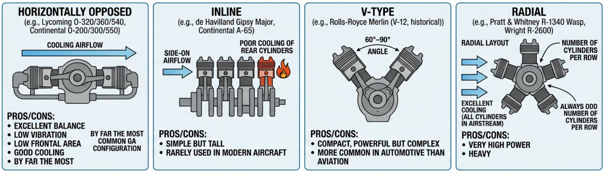
| Configuration | Characteristics | Examples |
|---|---|---|
| Horizontally Opposed | Cylinders in two banks, opposite each other. Excellent balance, low vibration, low frontal area, good cooling. By far the most common GA configuration. | Lycoming O-320/360/540, Continental O-200/300/550 |
| Inline | All cylinders in a single row. Simple but tall, poor cooling of rear cylinders. Rarely used in modern aircraft. | de Havilland Gipsy Major, Continental A-65 |
| V-type | Two banks of cylinders at 60°–90° angle. Compact, powerful, but complex. More common in automotive than aviation. | Rolls-Royce Merlin (V-12, historical) |
| Radial | Cylinders arranged in a star pattern around the crankshaft. Excellent cooling (all cylinders in airstream), very high power, heavy. Always odd number of cylinders per row. | Pratt & Whitney R-1340 Wasp, Wright R-2600 |
Firing Order
The firing order is the sequence in which cylinders fire. It is designed to:
- Distribute thermal stress — avoid adjacent cylinders firing consecutively
- Minimise vibration — balance the crankshaft loading
- Ensure smooth power delivery — evenly space power strokes
Typical firing orders:
- 4-cylinder opposed: 1-3-2-4 or 1-4-2-3
- 6-cylinder opposed: 1-4-5-2-3-6
- Radial (5-cylinder): 1-3-5-2-4 (every other cylinder around the circle)
In a 4-stroke engine, power strokes are spaced every 720° ÷ N of crankshaft rotation (where N = number of cylinders). For a 4-cylinder engine: 720° ÷ 4 = 180° between power strokes.
Printing is not available
Please view study notes online at part66online.com